Additional projects / Fluids & cooling
Microfluidic chips, valves, and prototypes
Small fluid channels, valves, and test chambers, including devices built from layered acrylic.
Open the numbered review →Chip collection and test chambers
Photos 377–383, 392–393
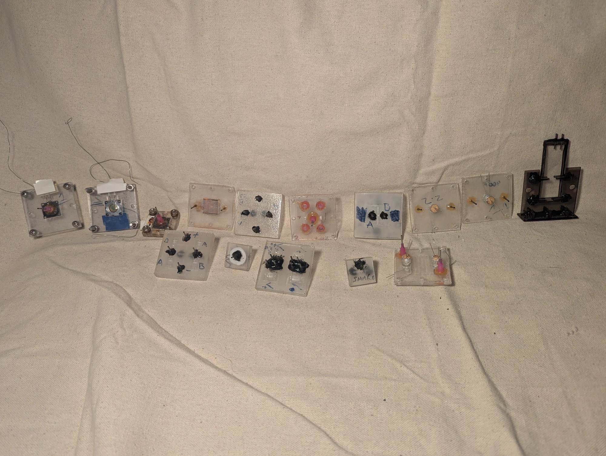
These homemade microfluidic chips guide small amounts of liquid through channels inside acrylic. I laser-cut or engraved the patterns, then sanded, cleaned, and bonded the stacked layers using heat and pressure. The collection includes one-way flow elements, pressure-controlled valves, heat exchangers, and winding channels for a fluorescent-dye display experiment.
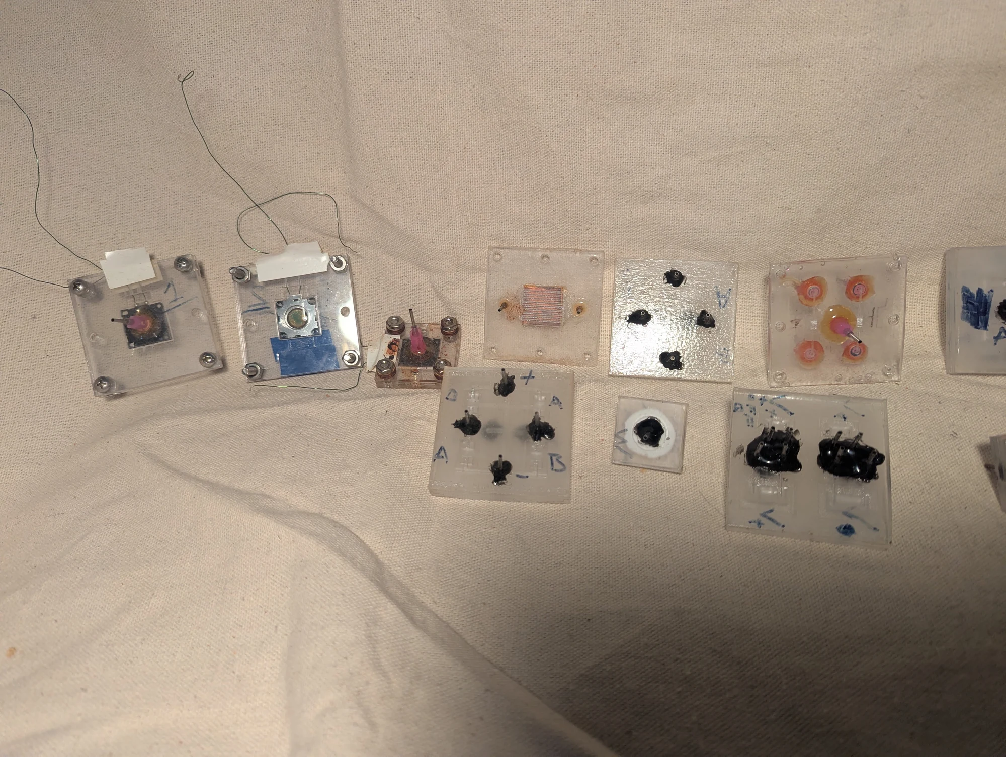
Another view of the microfluidic collection. Patterns engraved into acrylic became enclosed fluid paths when the layers were bonded together with heat and pressure. I used these prototypes to try different ways of routing ferrofluid and other liquids.
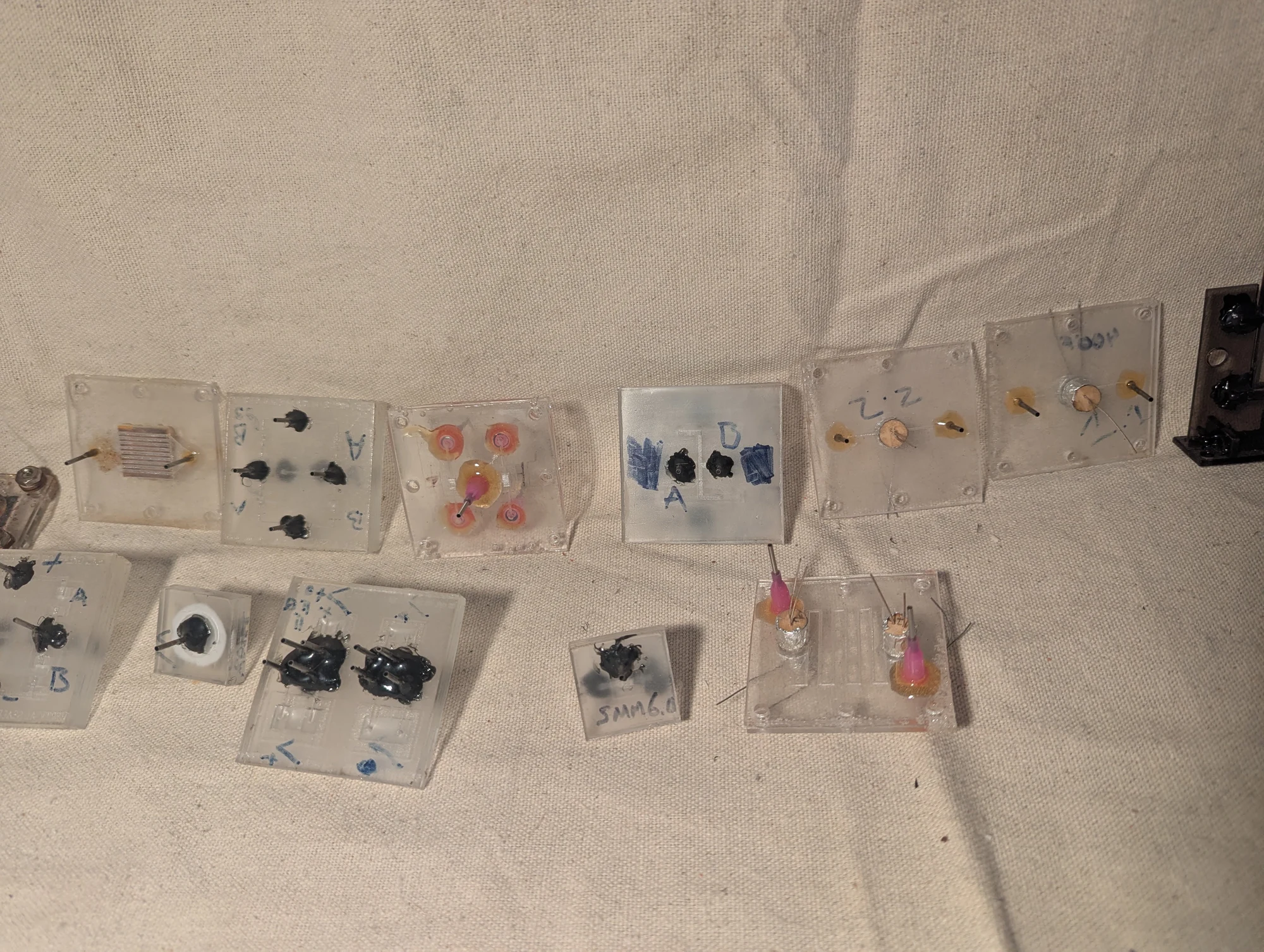
A closer view of the acrylic prototypes. Across the collection, I experimented with silicone flaps for one-way flow, flexible membranes for pressure-controlled valves, and optical sensing. These were separate trials of small fluid-handling components.
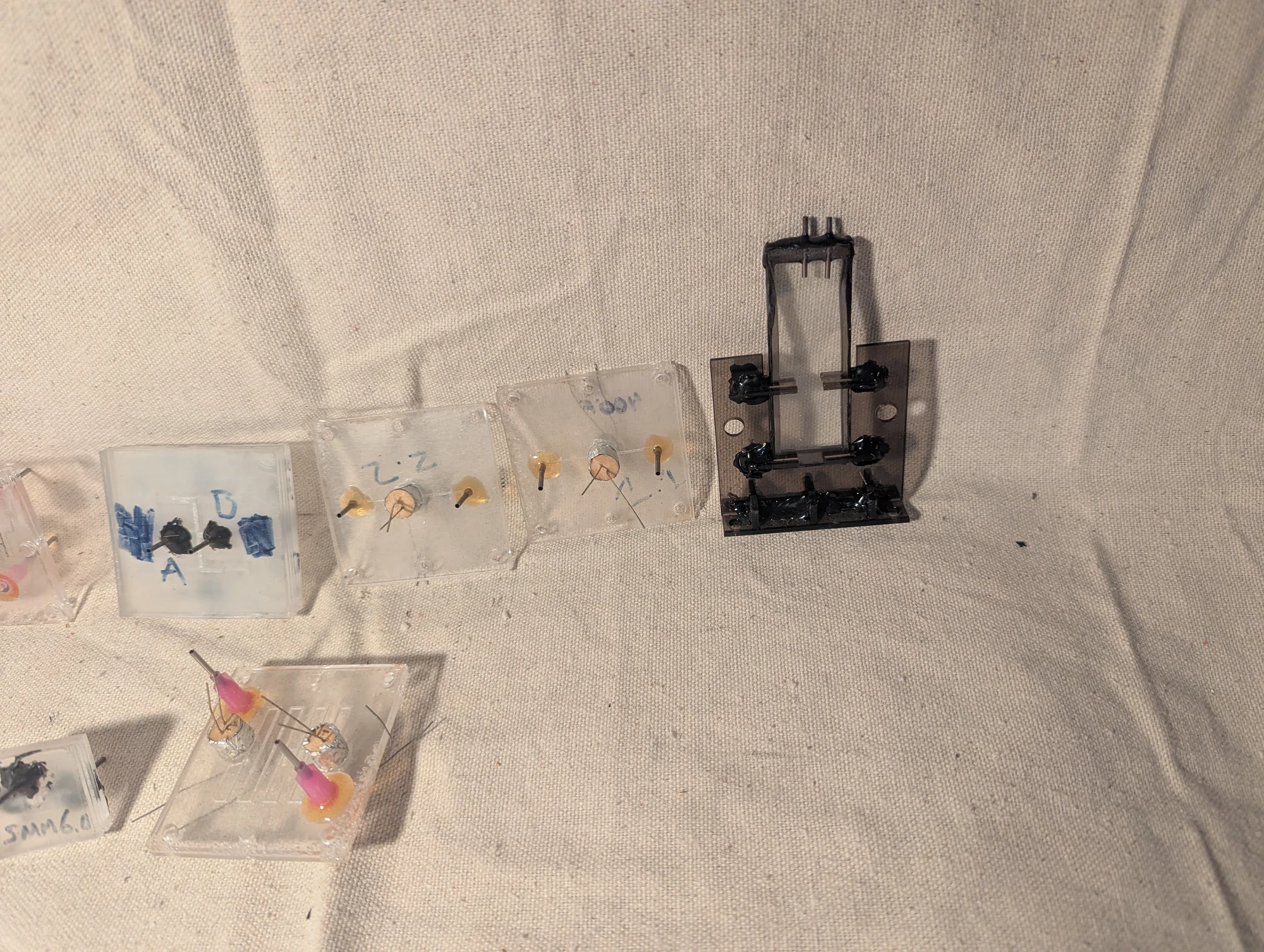
Part of the acrylic microfluidics collection. The broader project combined small fluid channels with pumps, sensors, and heat-transfer surfaces. Piezoelectric blowers supplied air pressure for some experiments, while light sensors helped detect moving fluid.
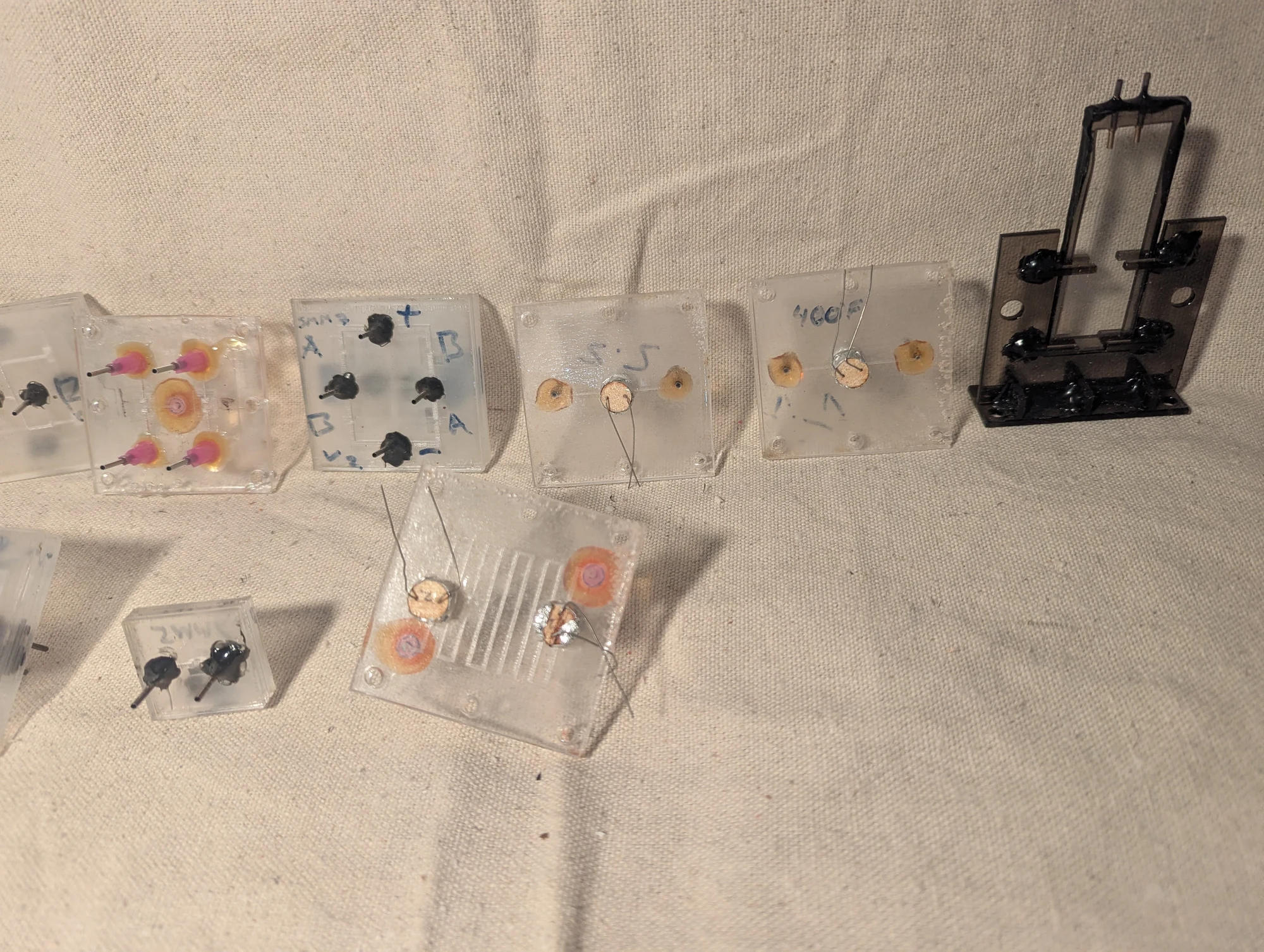
A further view of the stacked-acrylic prototypes and their supporting hardware. I used the same fabrication approach to explore several functions, including controlling flow and moving a small segment of fluorescent dye through a channel.
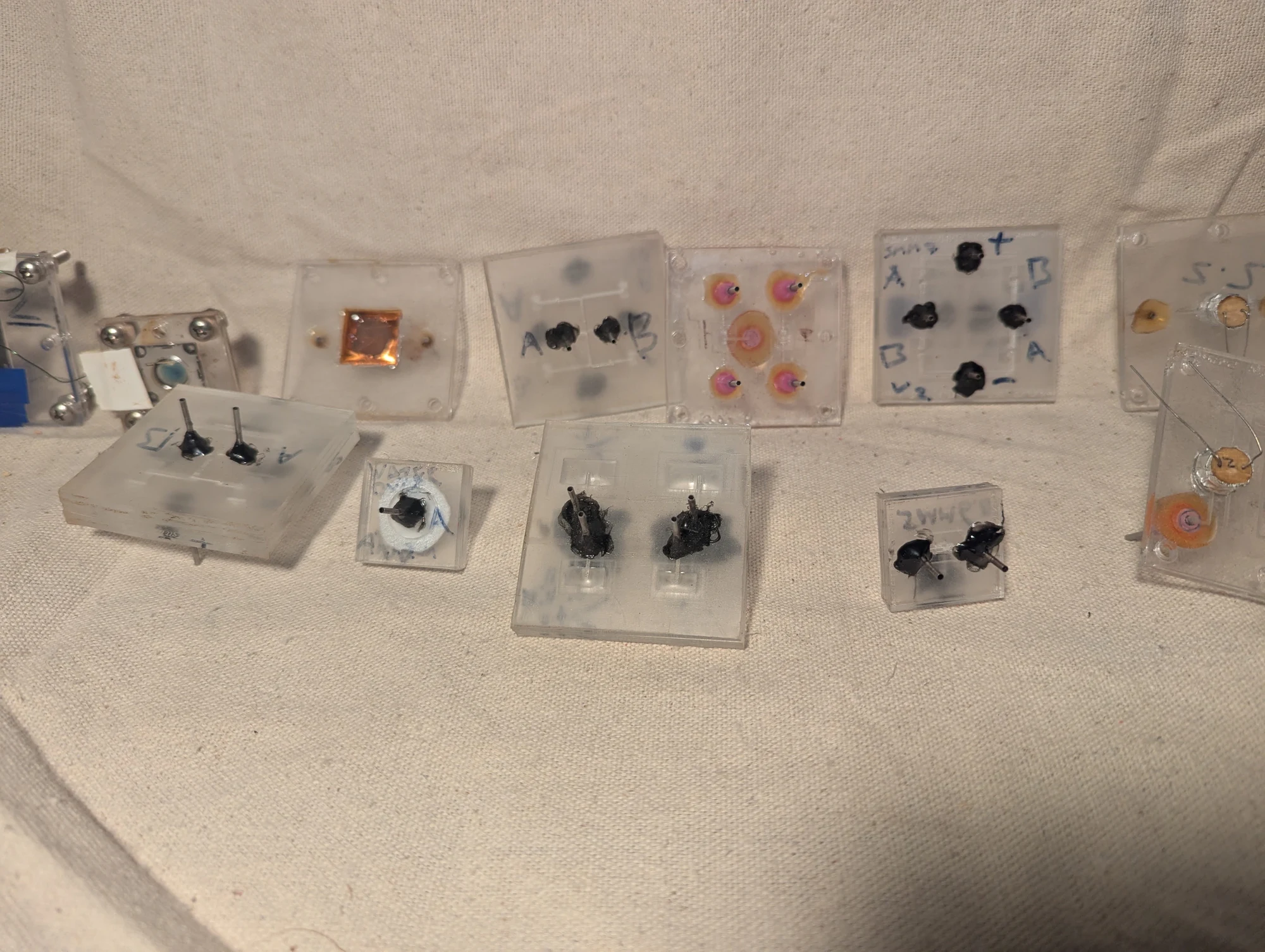
A selection of acrylic microfluidic prototypes with different internal layouts. Laser engraving let me try fine channel patterns before bonding the layers into enclosed devices. The designs supported experiments in fluid routing, valves, heat exchange, and optical detection.
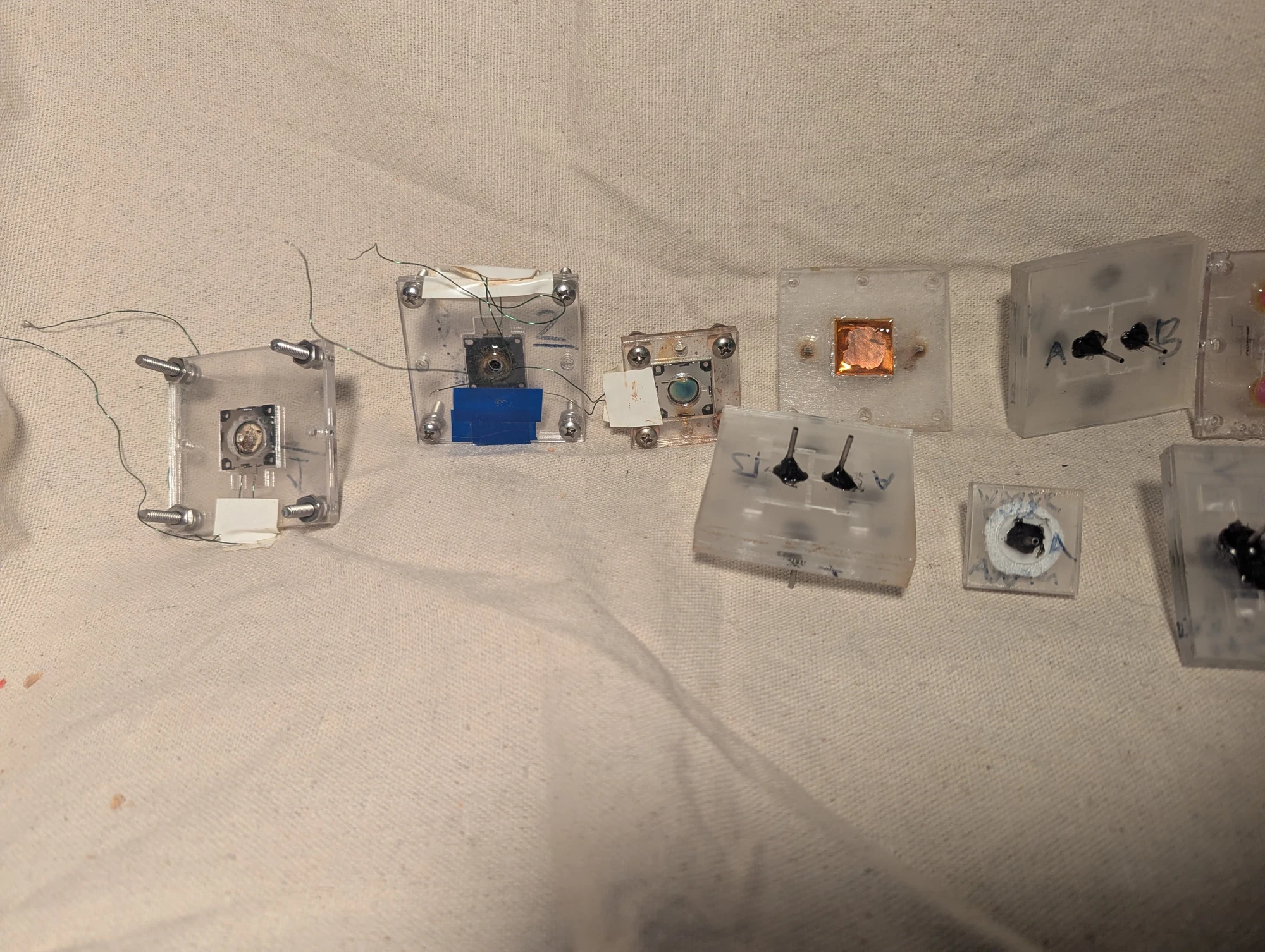
Another part of the microfluidic collection. Some designs incorporated copper surfaces so liquid could pass directly over a heat-transfer plate; others explored valves and sensing. These prototypes helped me investigate individual components before combining them into larger experiments.
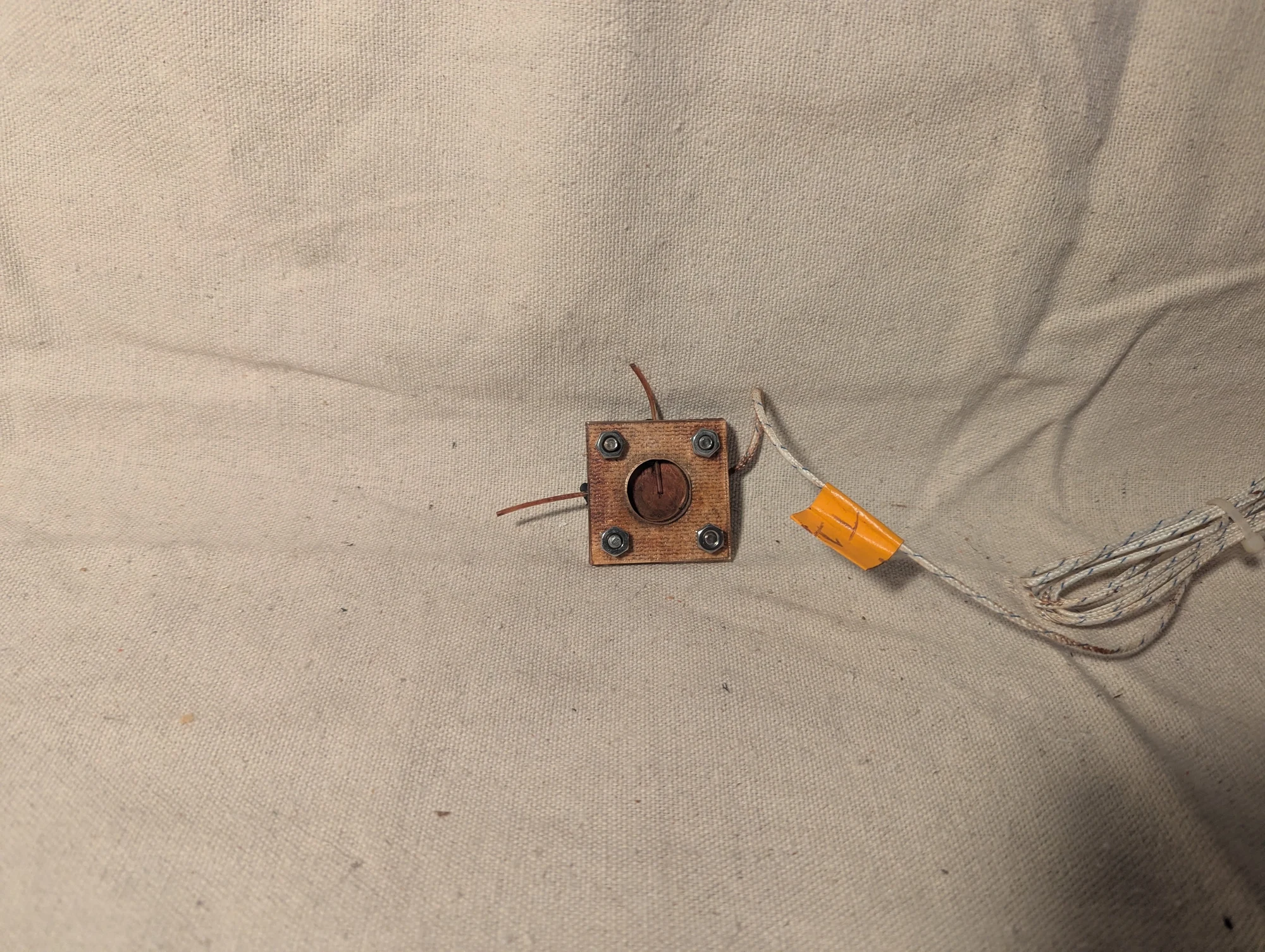
A microfluidic test chamber from this series of experiments. I believe it was used to investigate temperature changes, although I no longer recall the precise test configuration.
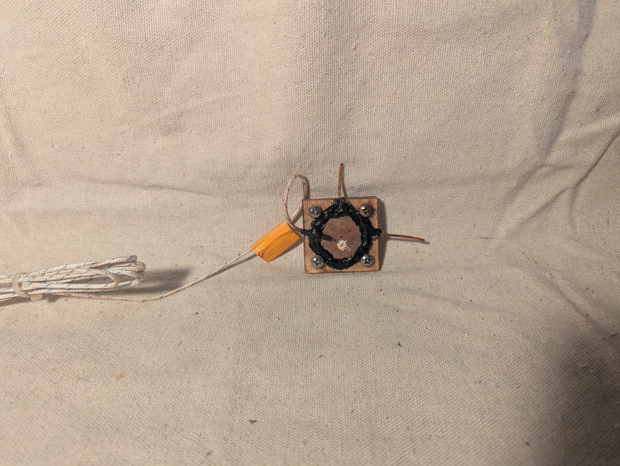
Another angle of the small fluid chamber and its connections. Its exact purpose is uncertain, but it appears to belong to the temperature-measurement experiments.
Pressure-controlled valves and fluidic H-bridge
Photos 384–387, 396–397
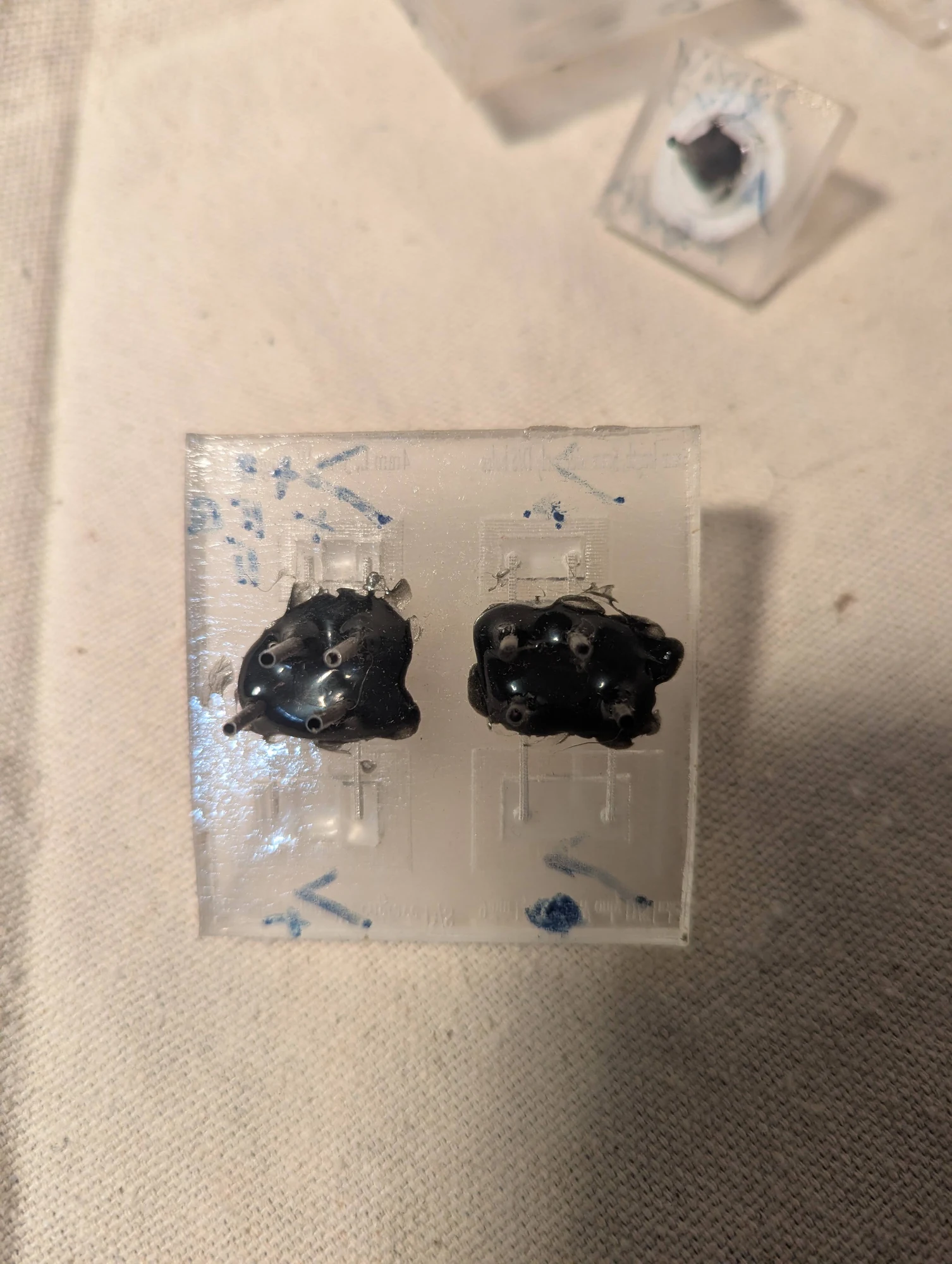
These miniature switches control liquid flow using a flexible silicone membrane. Each has an inlet, an outlet, and a separate pressure connection. Applying pressure expands the membrane into the flow path, blocking the connection between the other two ports.
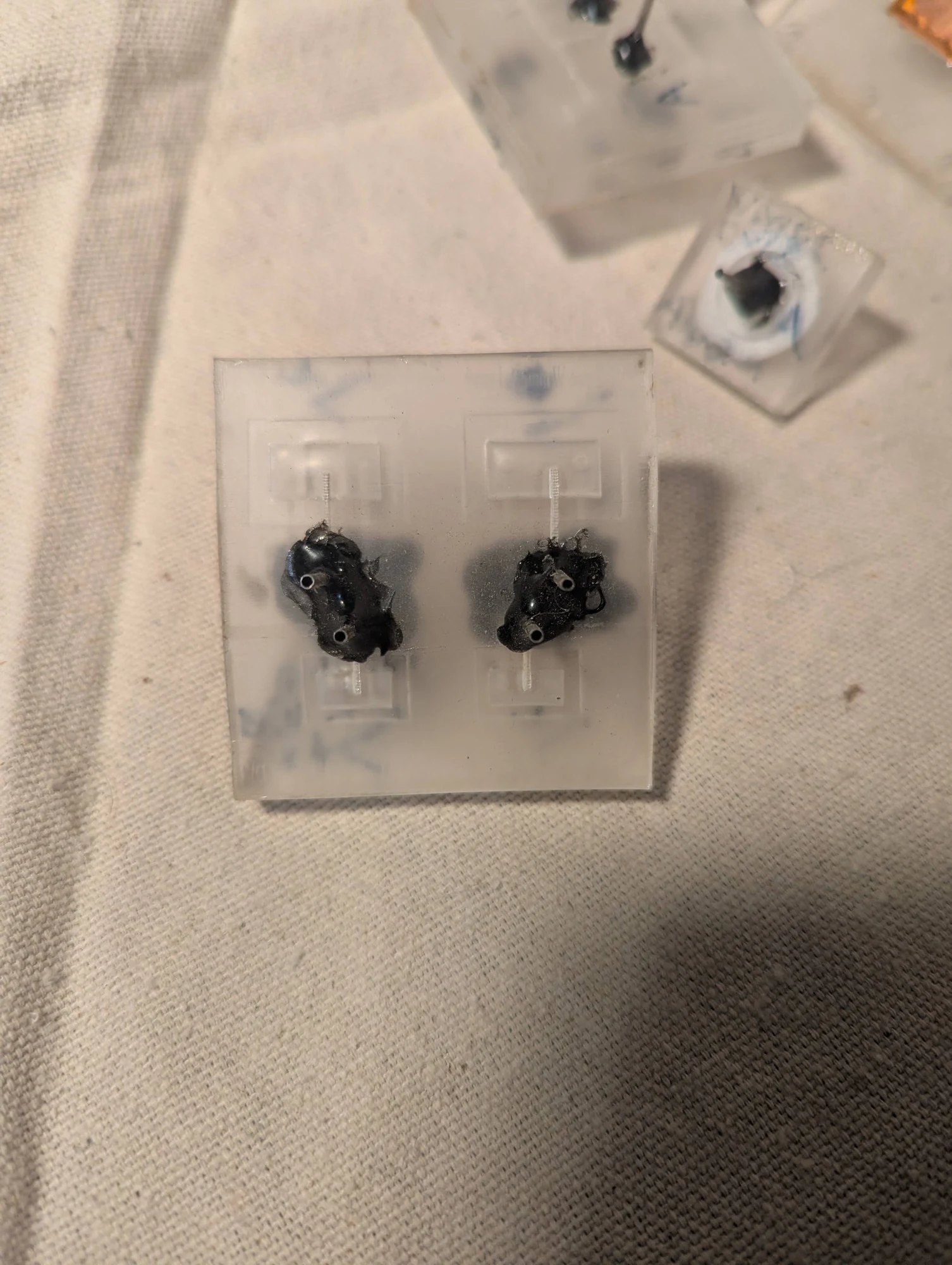
Another view of the microfluidic switches. A separate pressure signal moves a silicone membrane to close the liquid path, providing a way to control flow without placing an electrical switch in the fluid.
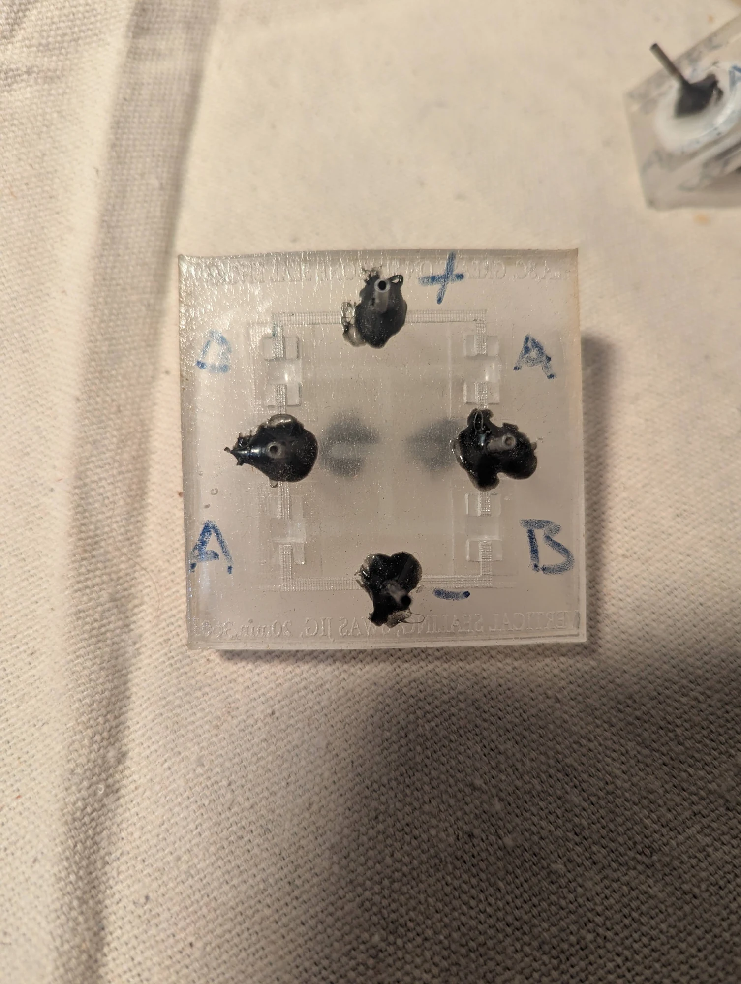
Four pressure-controlled valves combined into a fluidic H-bridge. Borrowing the layout of an electronic switching circuit, this prototype explored how several small valves could work together to select different paths for liquid flow.
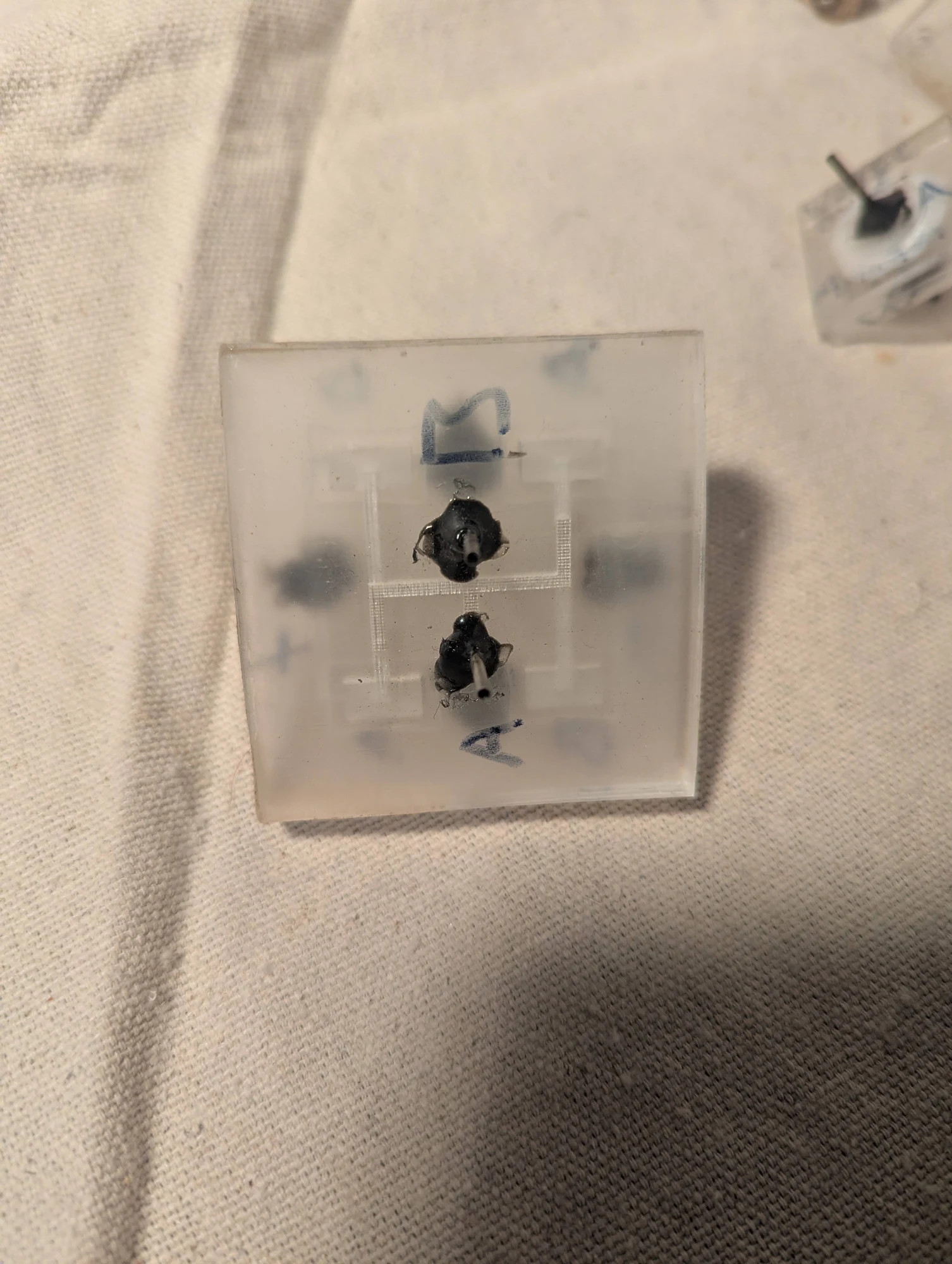
An alternate view of the four-valve assembly. The H-bridge name refers to the arrangement of interconnected flow paths; the switching elements here control fluid rather than electrical current.
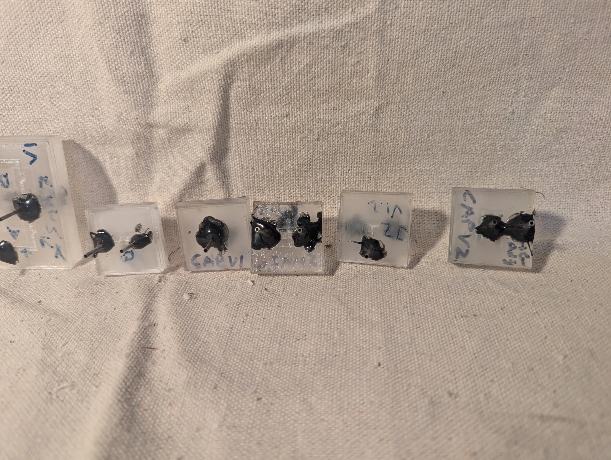
A collection of pressure-controlled valves and one-way flow elements. I thought of these as fluidic versions of MOSFETs and diodes: a control signal could close a flow path, while a flexible flap could allow flow in one direction and resist it in the other.
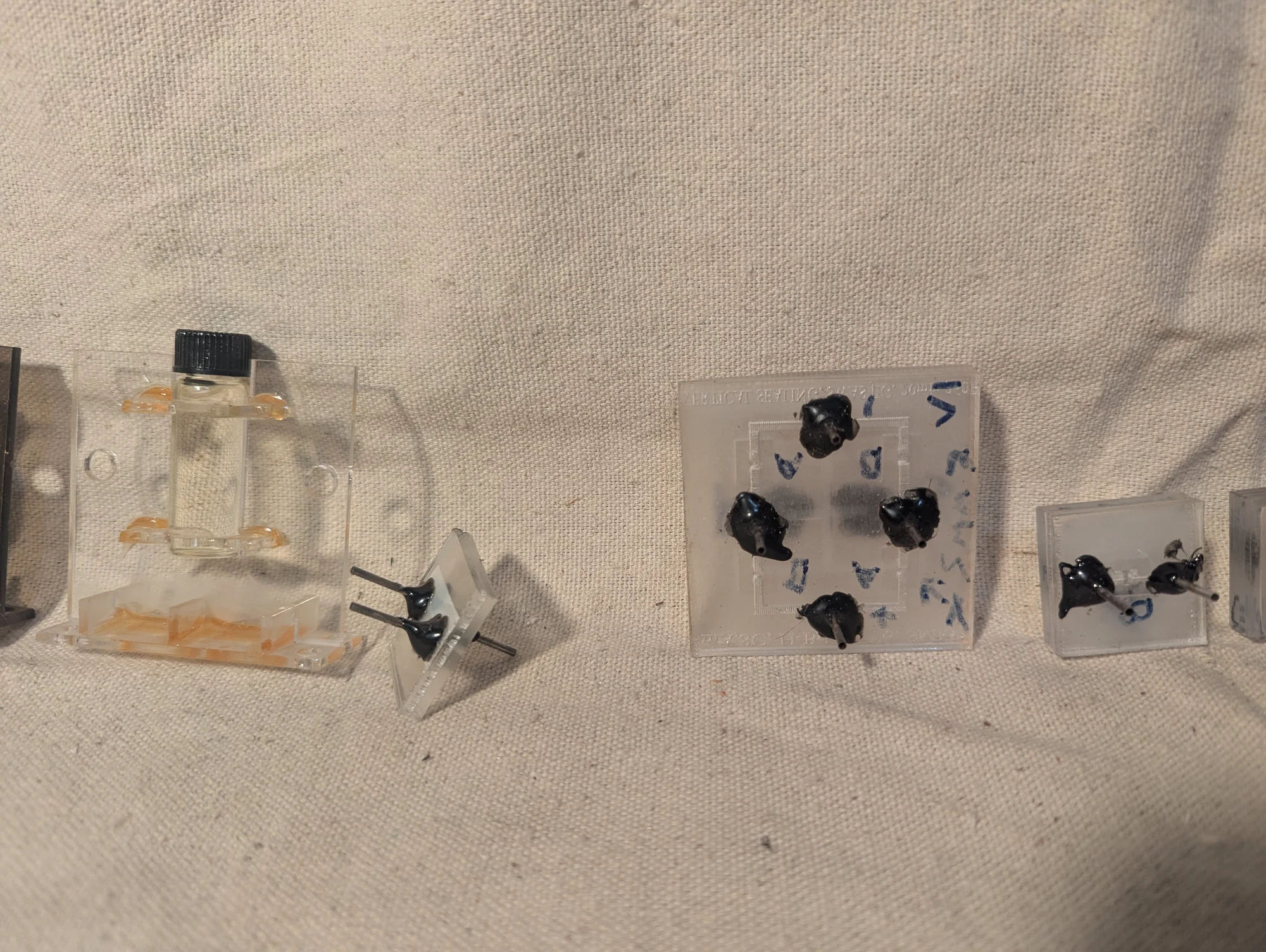
Another view of the experimental valves and one-way elements. The comparison with electronic components helped me think about combining simple fluid-control functions into more complex devices.
Screw-operated pinch valves
Photos 394–395
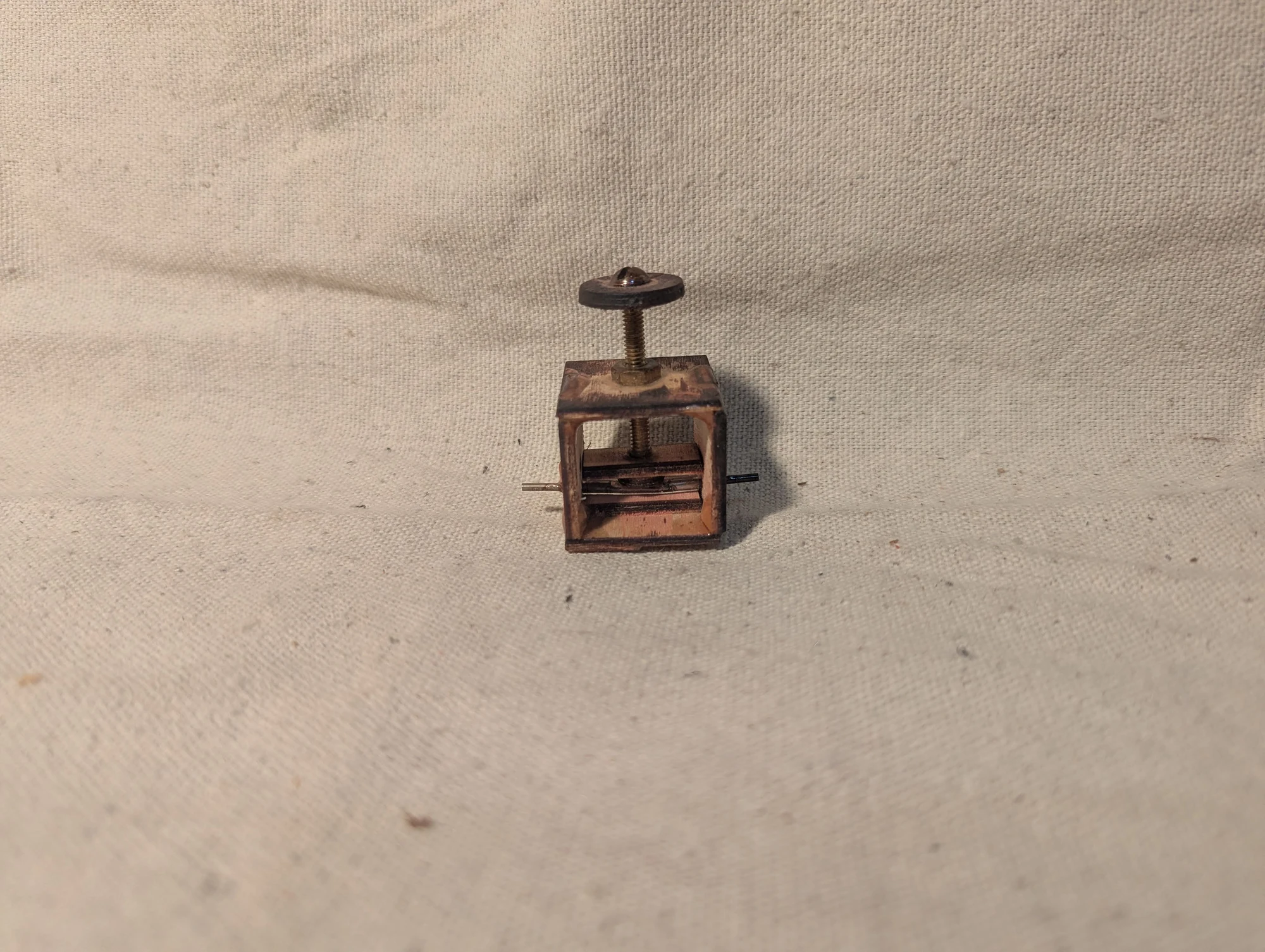
A simple mechanical valve for small fluid lines. Turning the screw presses against flexible Tygon tubing, narrowing or closing the passage to control flow.
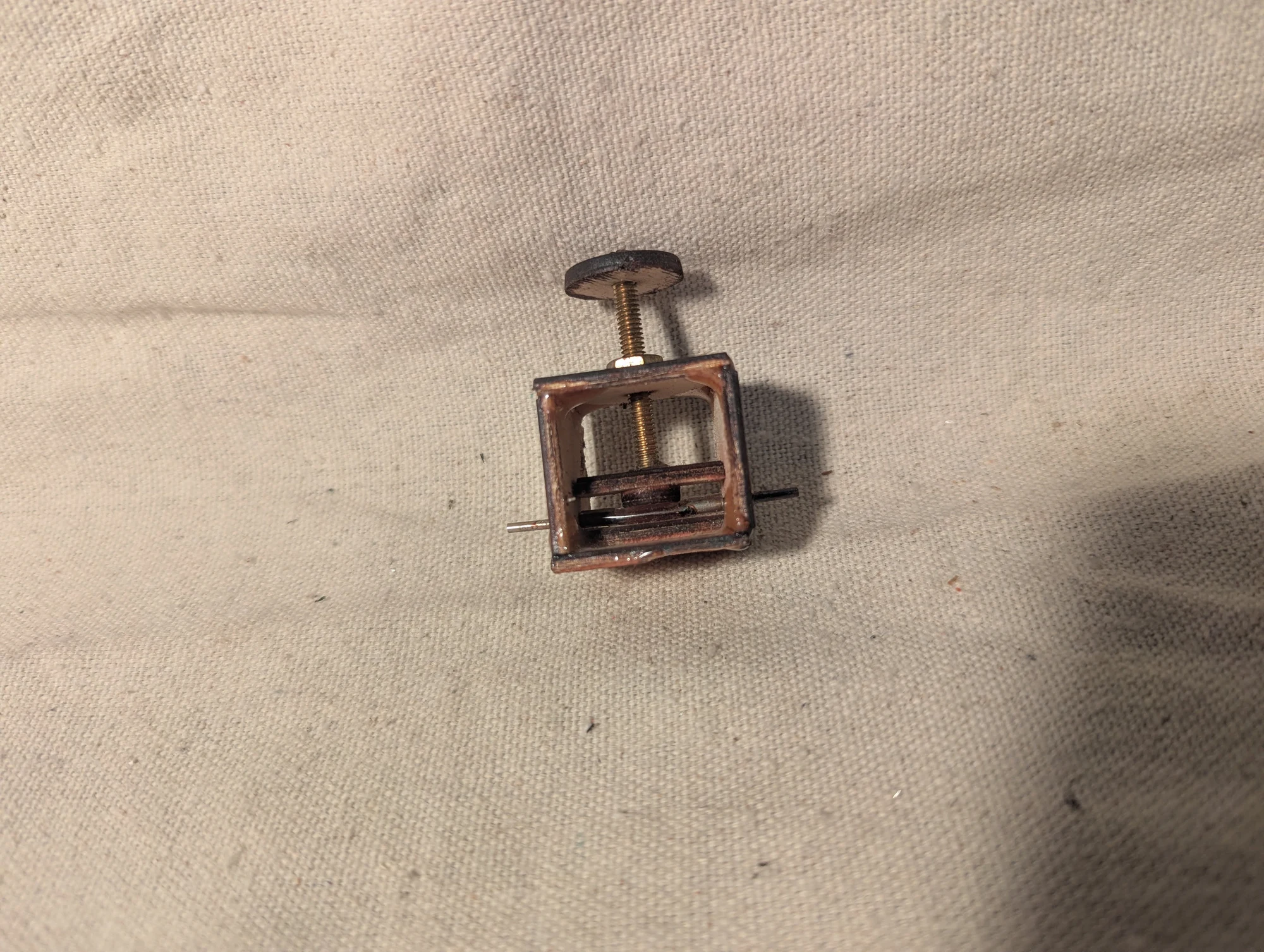
An alternate view of the pinch valve. The screw adjusts how firmly the flexible tube is compressed, providing a manual way to restrict or stop the liquid passing through it.
Other microfluidic prototype
Photo 416
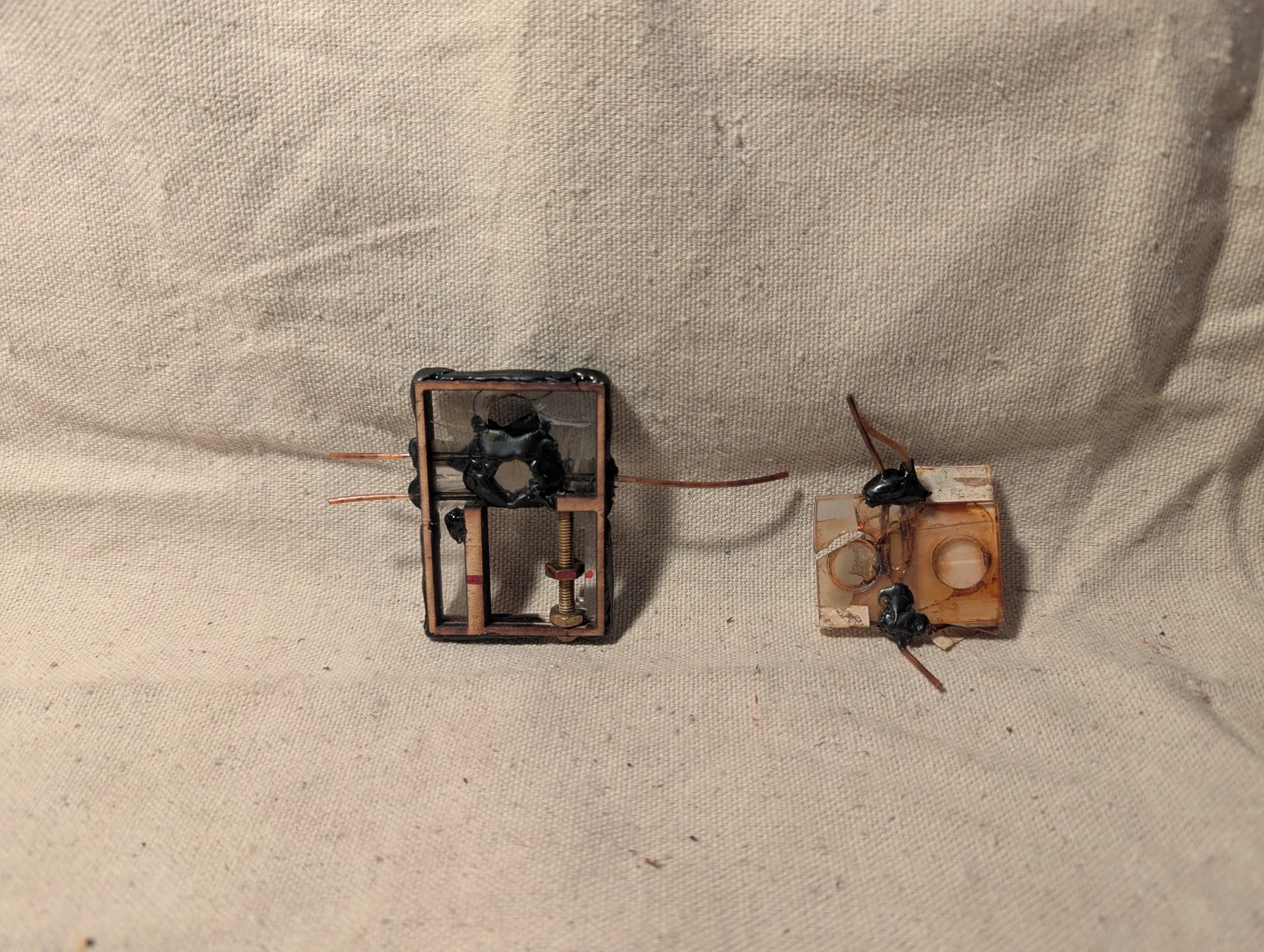
I have grouped this adjustable experimental assembly with my microfluidics work. I no longer recall its exact purpose.
Bonding fixtures
Photos 443–444
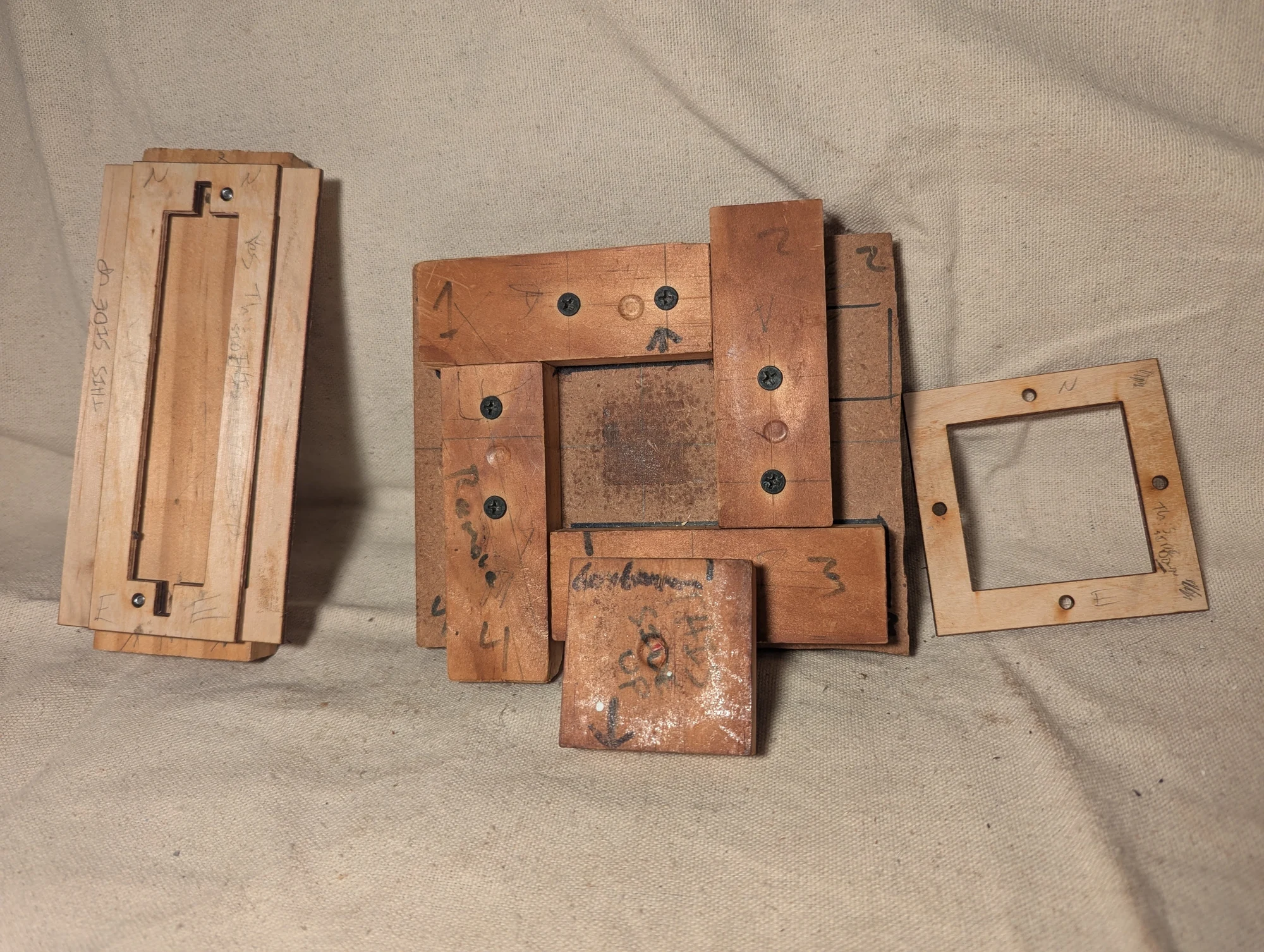
Jigs used to hold acrylic microfluidic layers together during bonding. After sanding and cleaning the pieces, I stacked them in a fixture, heated the assembly in an oven, and compressed the layers with a clamp. The square fixture was my main jig; the longer version accommodated elongated chips.
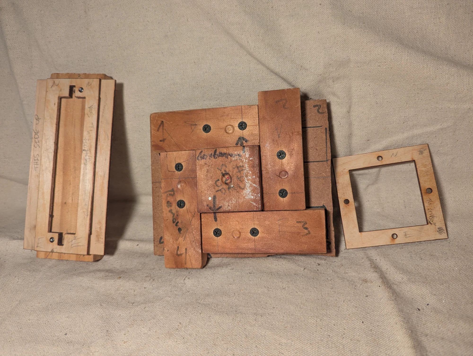
Another view of the fixtures used to align and compress heated acrylic layers. Different fixture shapes accommodated the square and elongated microfluidic devices.
Earlier bolted devices
Photos 477–478
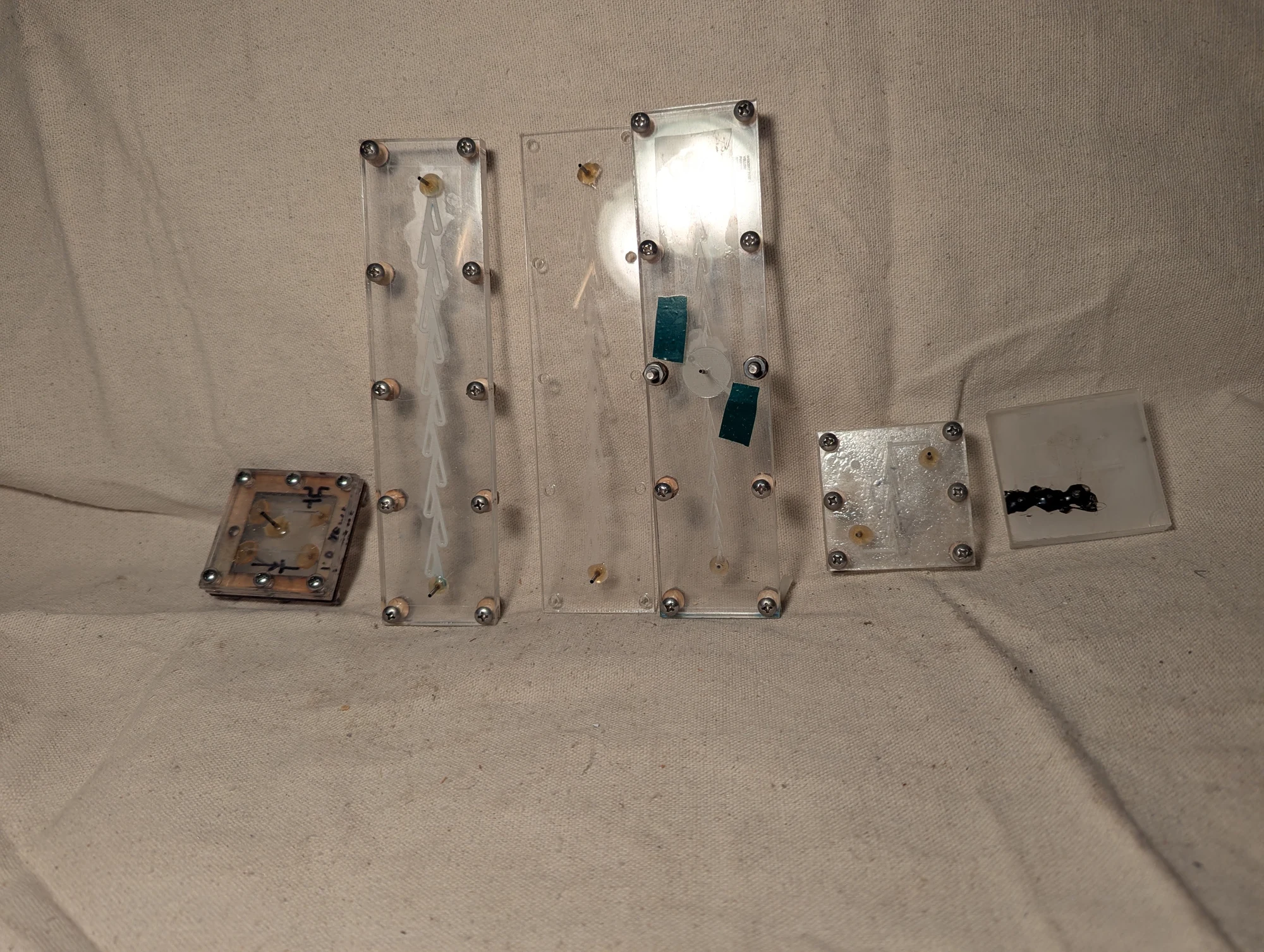
Early acrylic microfluidic devices, including Tesla valves: channel shapes intended to resist flow more in one direction than the other without moving parts. Before I developed heat-and-pressure bonding, I held thicker acrylic layers together with bolts and thin silicone gaskets. The collection may also include early pressure-controlled fluidic switches.
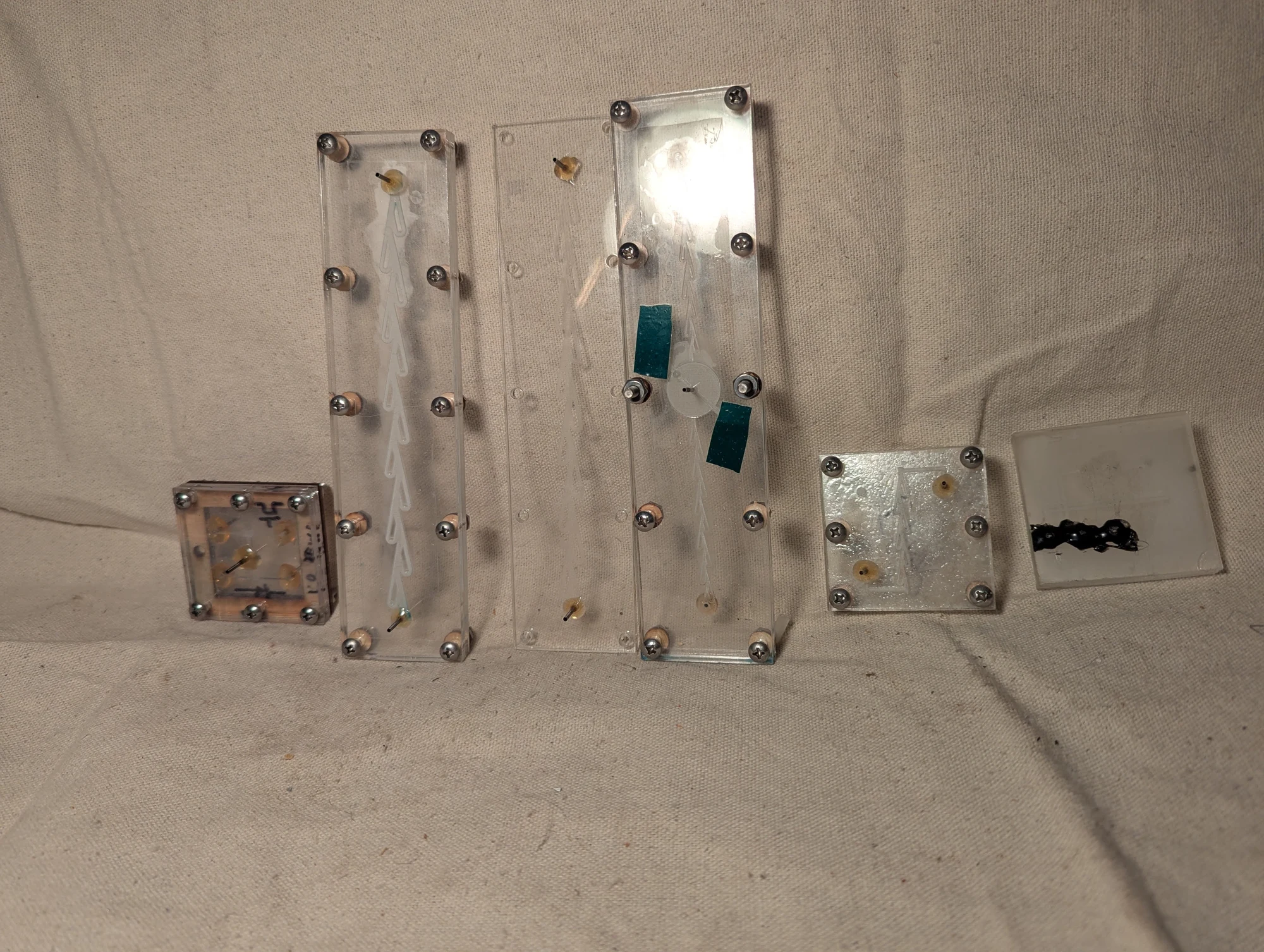
Another view of the Tesla-valve and microfluidic experiments. These assemblies used bolted acrylic plates and silicone sheets to seal the layers, preceding my later method of bonding thin acrylic chips with heat and pressure.