Additional projects / Optics & light
Fiber-optic coupling and wavelength experiments
Experiments in sharing light between fibers, using fluorescence, and manually selecting an output wavelength.
Open the numbered review →Fiber coupling and fluorescent bead
Photos 430, 432, 434–435
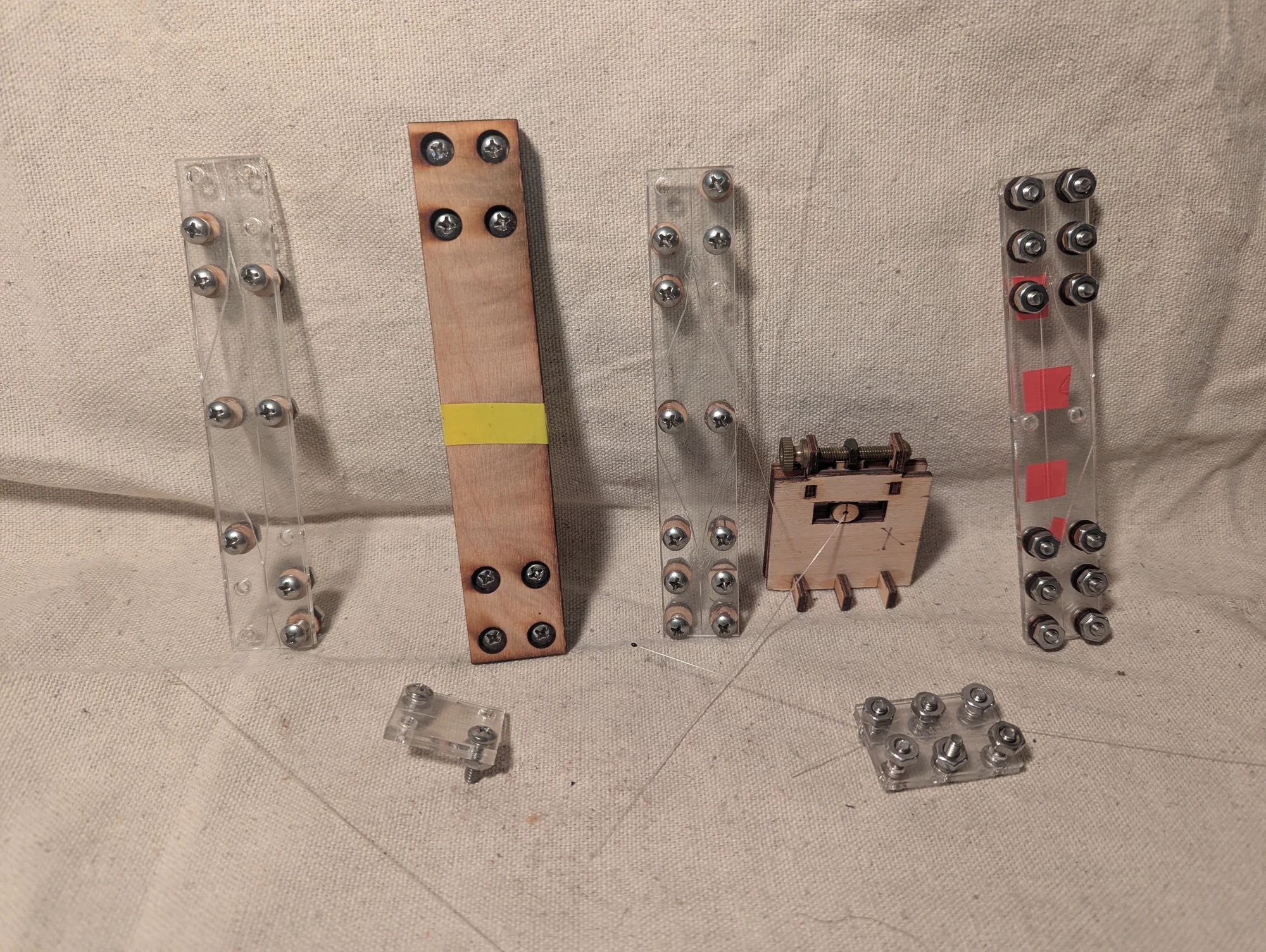
Experimental components for a fiber-optic interferometer. Engraved channels in acrylic plates held the fibers in position while I explored ways to split and combine their light signals. The fiber ends were placed against one another with index-matching gel intended to improve light transfer across the joints.
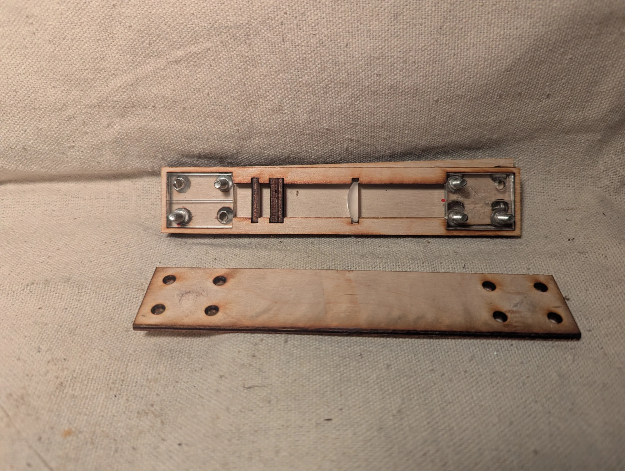
One fiber carried ultraviolet light to an epoxy bead containing fluorescent dye, causing the bead to emit colored light. A small lens was intended to collect that light and focus it onto the end of a second fiber. This prototype explored coupling the fluorescent output back into an optical fiber.
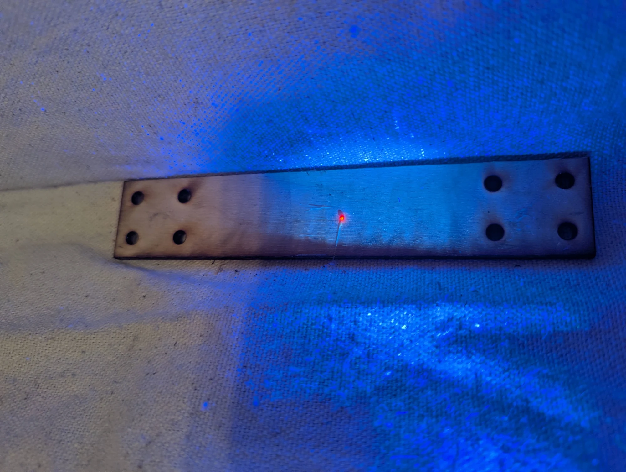
The epoxy bead glowing under ultraviolet illumination. Its reddish fluorescence shows the light-emitting material used in the fiber-coupling experiment.
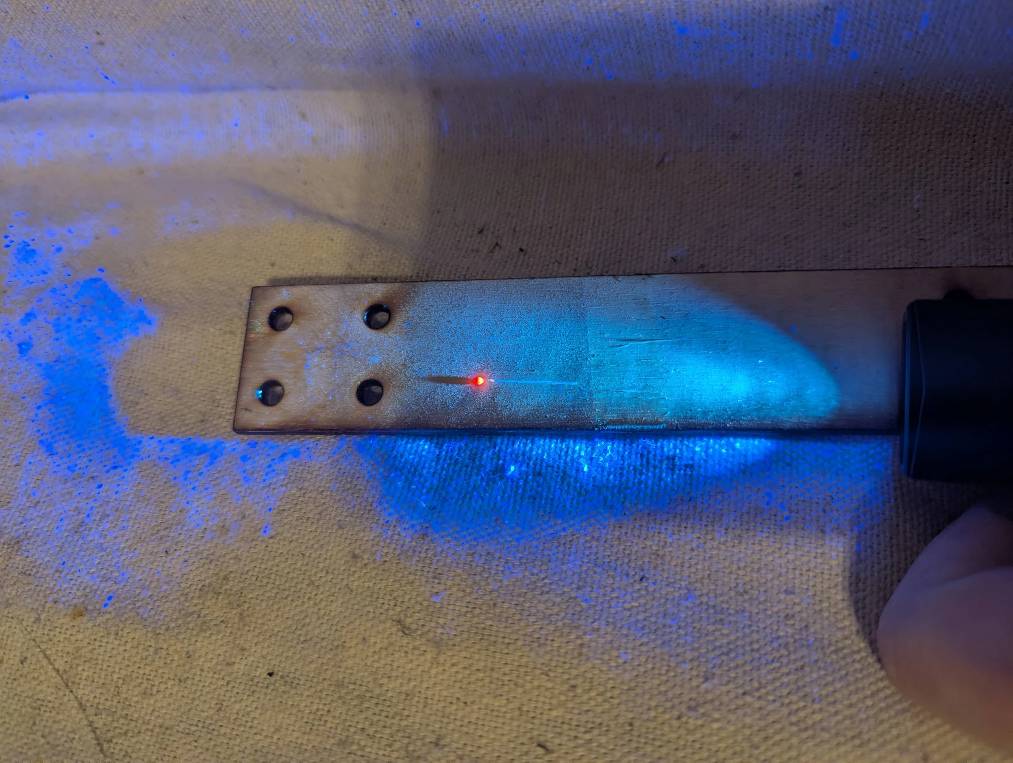
Another view of the fluorescent bead under ultraviolet illumination, within the optical assembly.
Wavelength selector
Photos 445–449
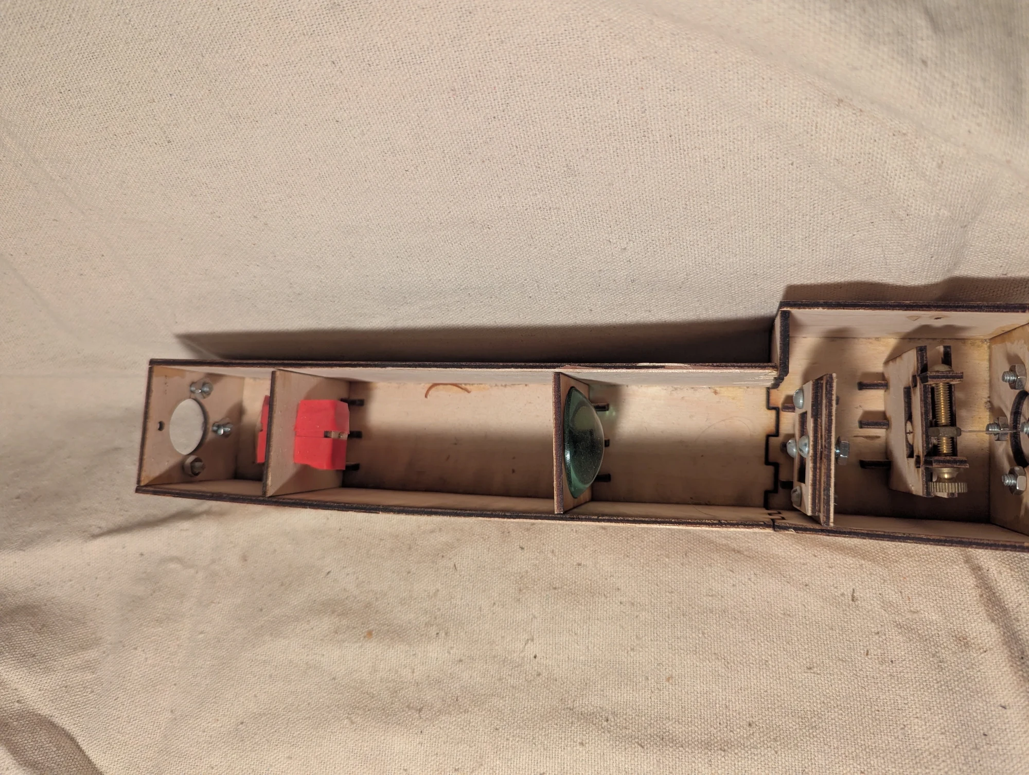
An optical prototype that used ultraviolet light to excite red, green, and blue fluorescent fibers. A lens and diffraction grating spread the resulting light by wavelength, and a screw-driven slider positioned a receiving fiber to collect a selected color. The goal was to change the output wavelength while retaining the information carried by changes in the incoming UV light.
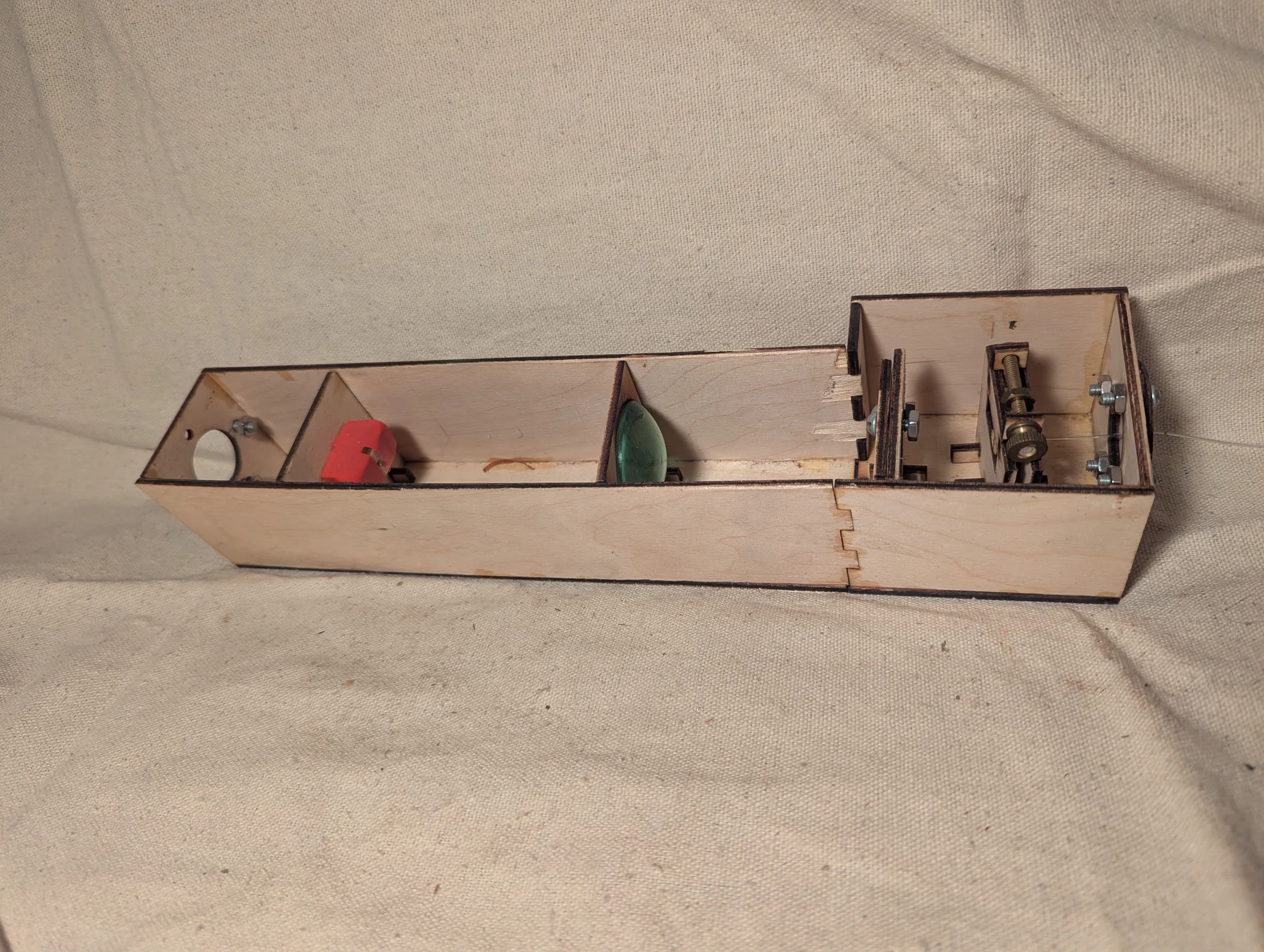
Another view of the optical bench. Fluorescent fibers converted ultraviolet excitation into visible light, and the adjustable receiving fiber collected a selected part of that light after it passed through the optics. The selected wavelength could be changed manually.
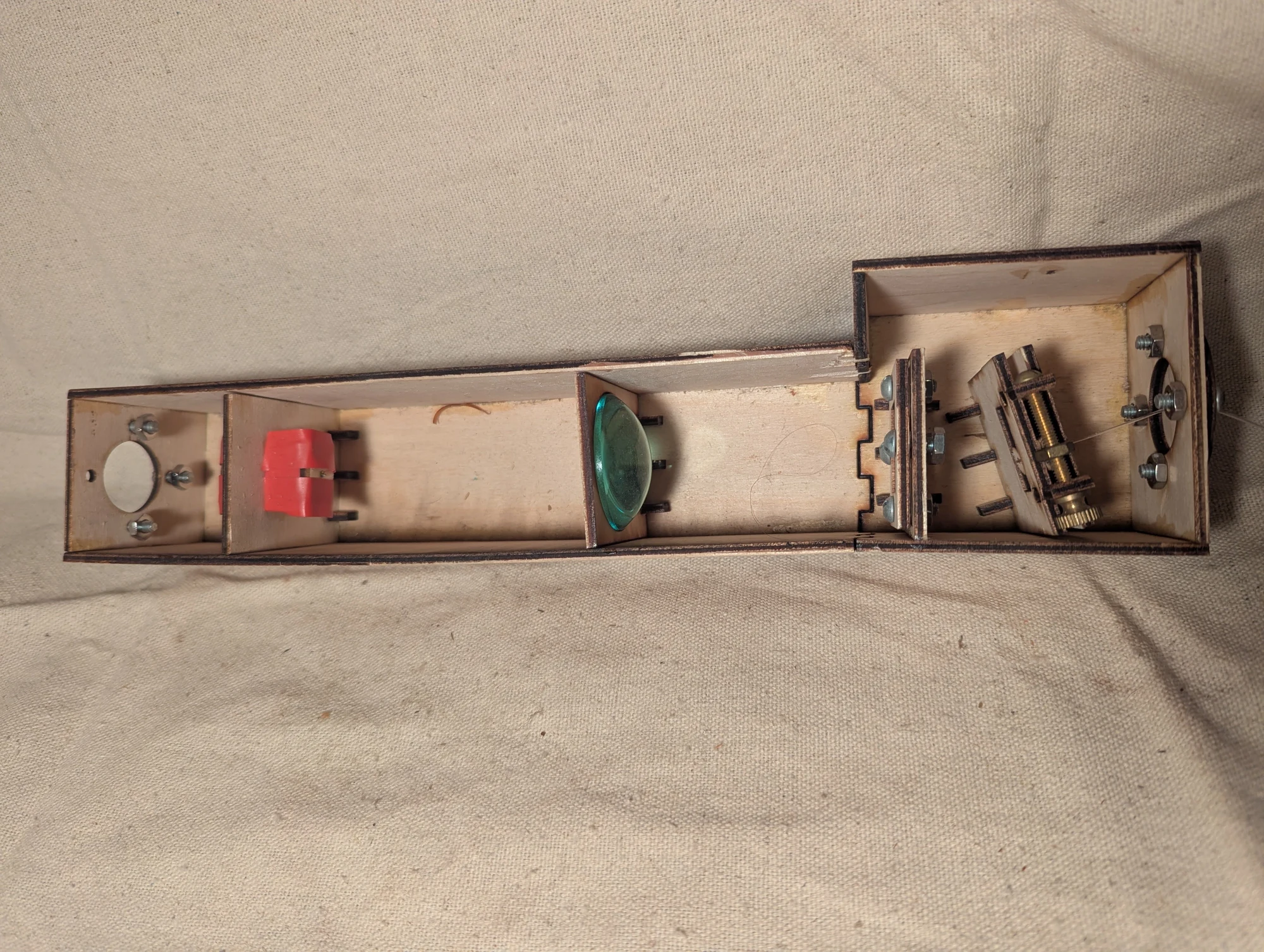
The bolt-and-nut adjustment moved the receiving fiber across the separated light. Changing the slider position selected a different wavelength range from the fluorescent source.
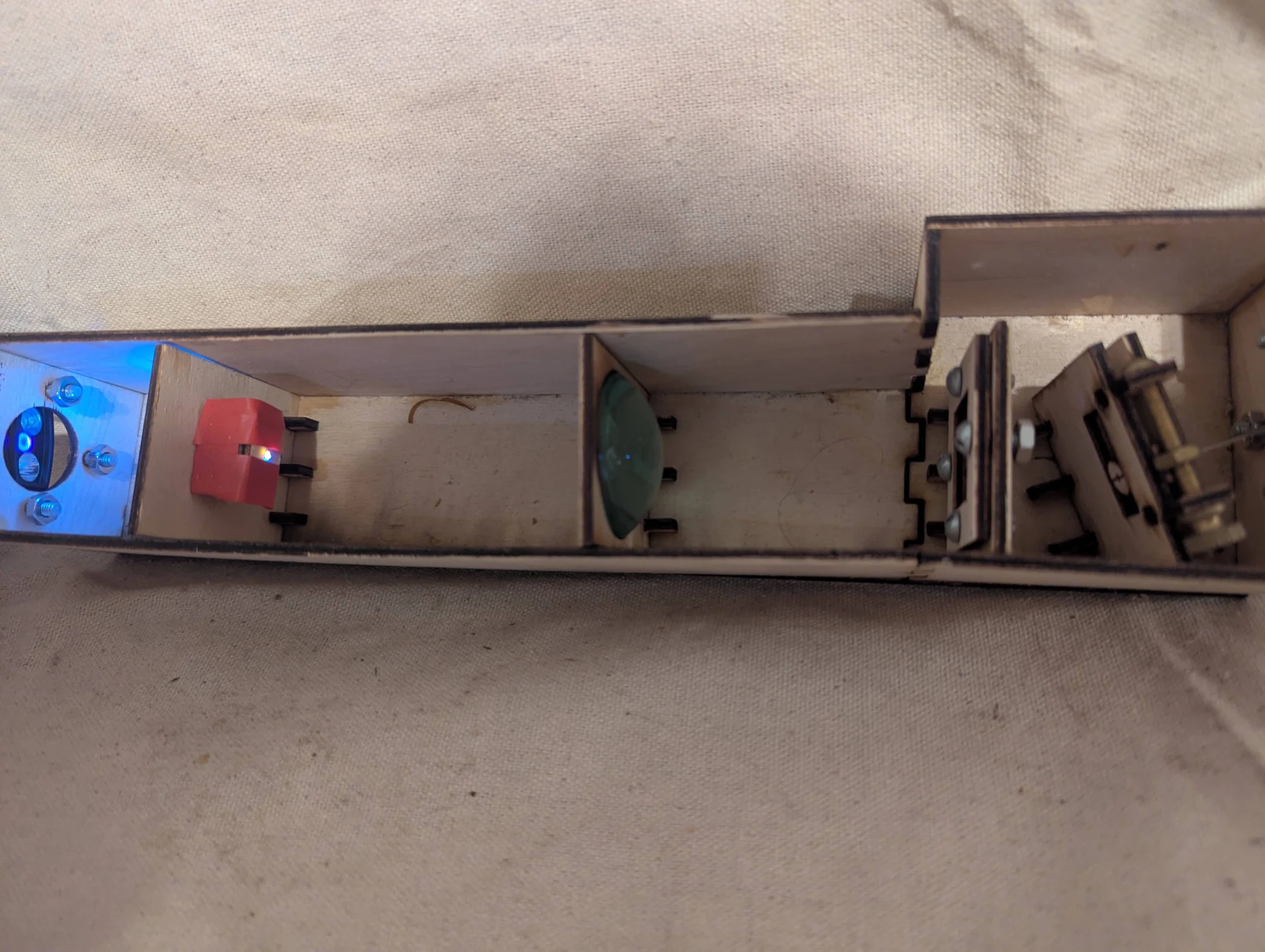
The fluorescent source illuminated with ultraviolet light. The intended application was to carry an optical signal into a different wavelength range, with the output color chosen by moving the receiving fiber. This view shows the mixed-color source and the manually adjustable optical assembly.
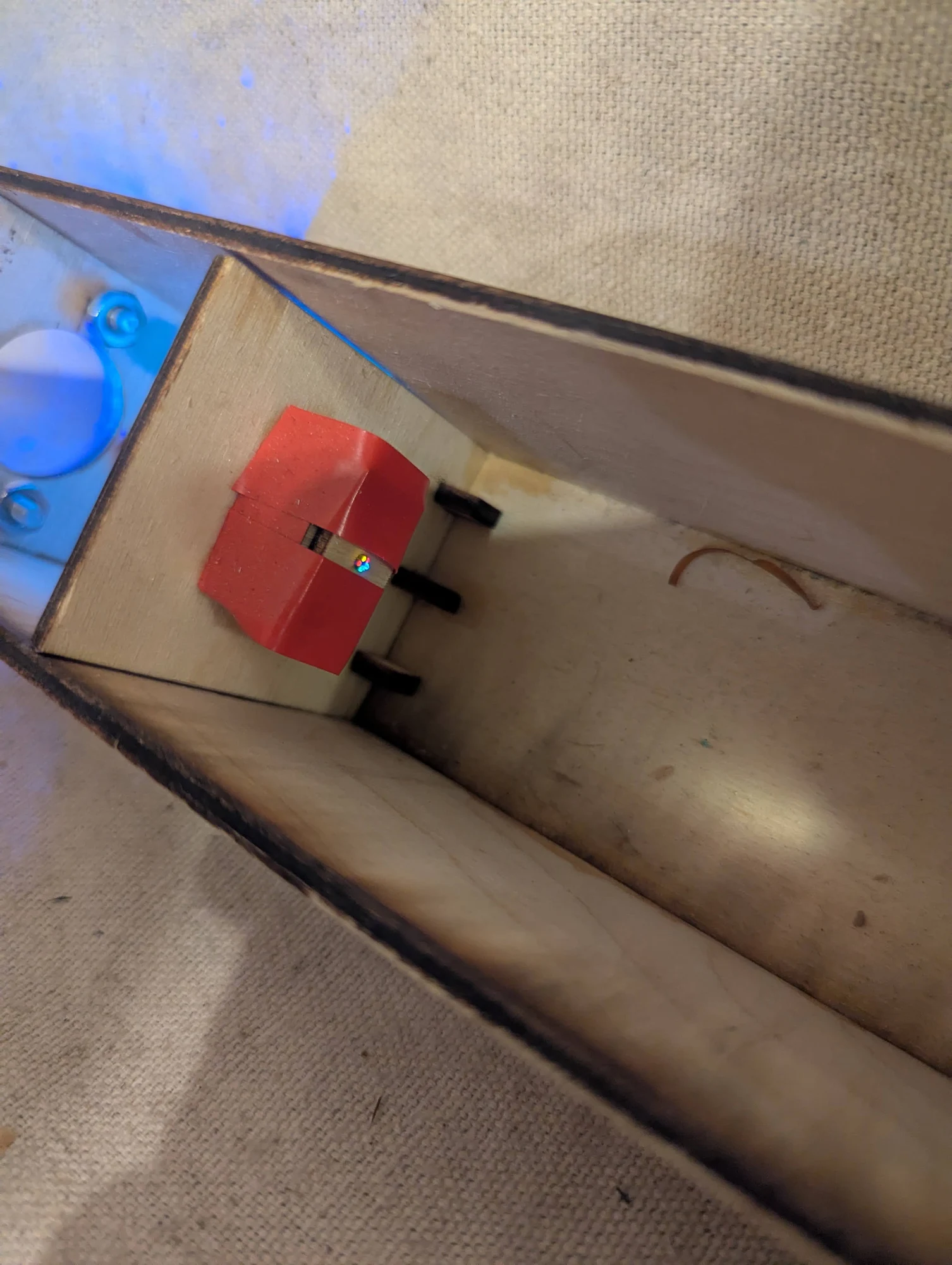
A close view of the red, green, and blue fluorescent fibers used as a roughly white, mixed-color light source. I recall power consumption being a reason for using UV-excited fluorescence instead of a tungsten lamp.
Fiber-twisting jig
Photos 480–481
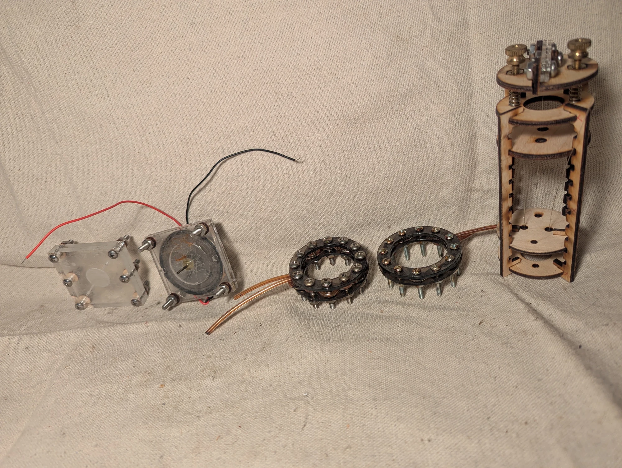
Among these assorted parts, the device on the right is a jig for pulling and twisting optical fibers together, then holding the arrangement with epoxy. The goal was to bring the fibers into close contact so light could pass between them. I eventually switched to commercially made fiber splitters, which were easier to use and gave better results.
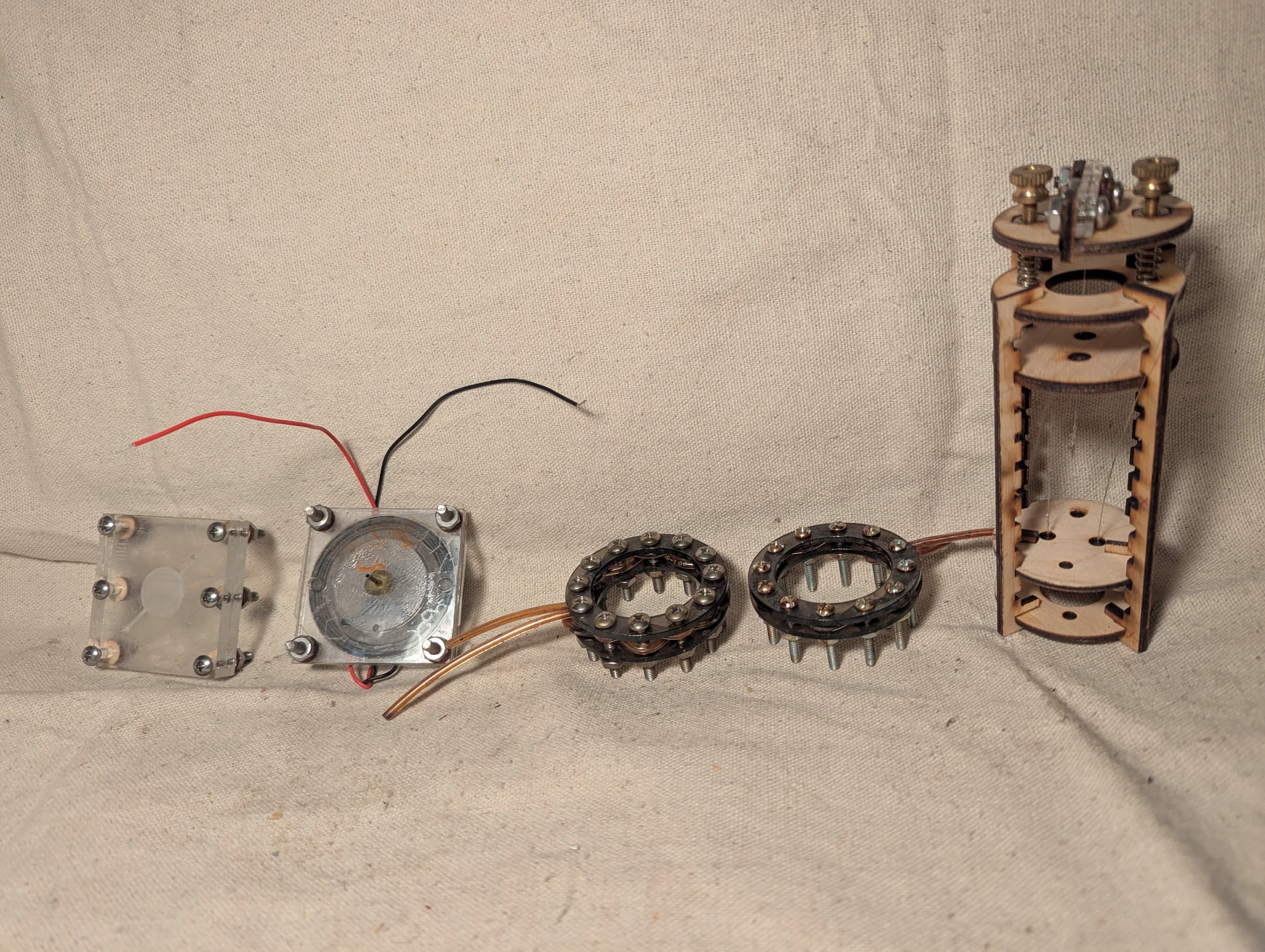
Another view of the assorted experimental hardware and the fiber-twisting jig at the right. The jig was part of an attempt to make a small optical splitter by bringing fibers together and fixing their arrangement with epoxy.
Fluorescent epoxy materials
Photos 490–496
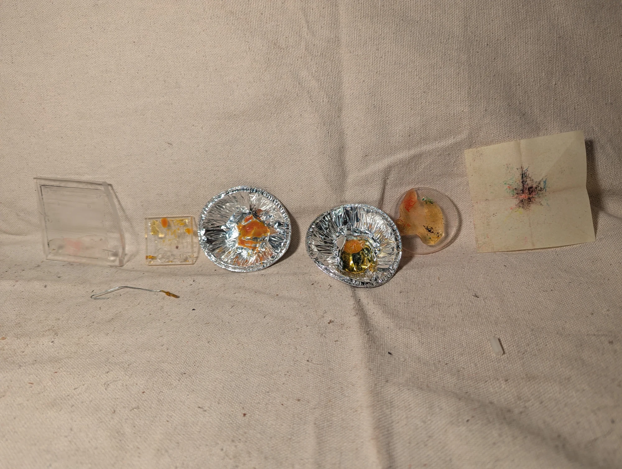
Samples made by mixing fluorescent dyes into epoxy. I used this material for the small glowing bead at the end of a fiber in the earlier optical experiment. I also pressed fluorescent epoxy into engraved acrylic patterns to explore different illuminated shapes.
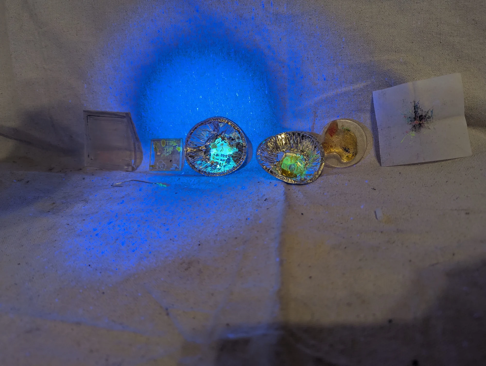
The fluorescent epoxy samples illuminated with ultraviolet light, showing their colored emission. These material experiments supported both the fiber-end bead and the filled acrylic patterns.
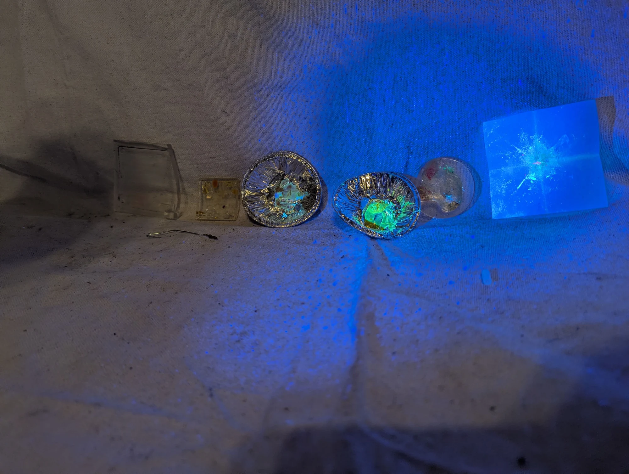
Another view of the epoxy-and-dye experiments under ultraviolet illumination. The samples include small cast pieces and patterns formed in acrylic.
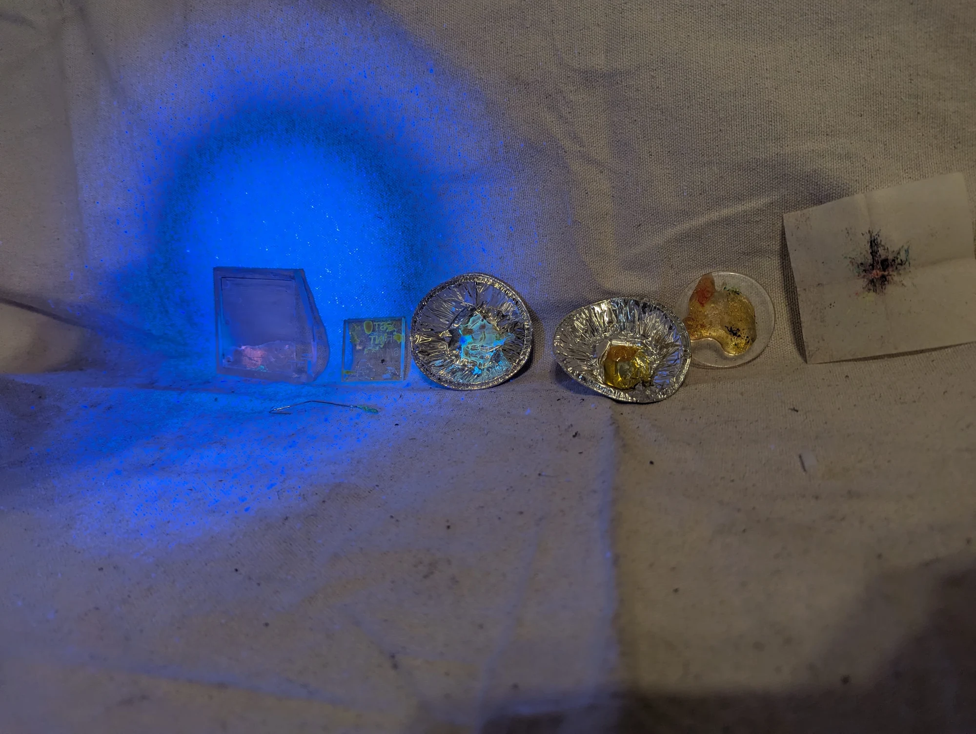
A further view of the fluorescent epoxy samples. Illuminating the pieces with ultraviolet light let me see how the colored material appeared in different shapes.
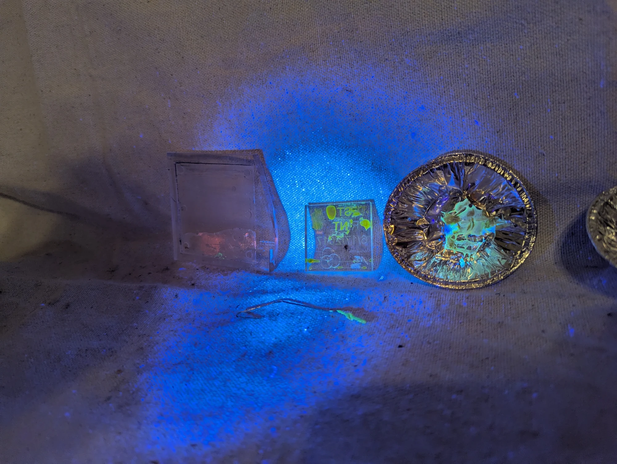
A closer view of the epoxy samples and filled acrylic patterns under ultraviolet light. These were exploratory trials of fluorescent materials for small optical and decorative elements.
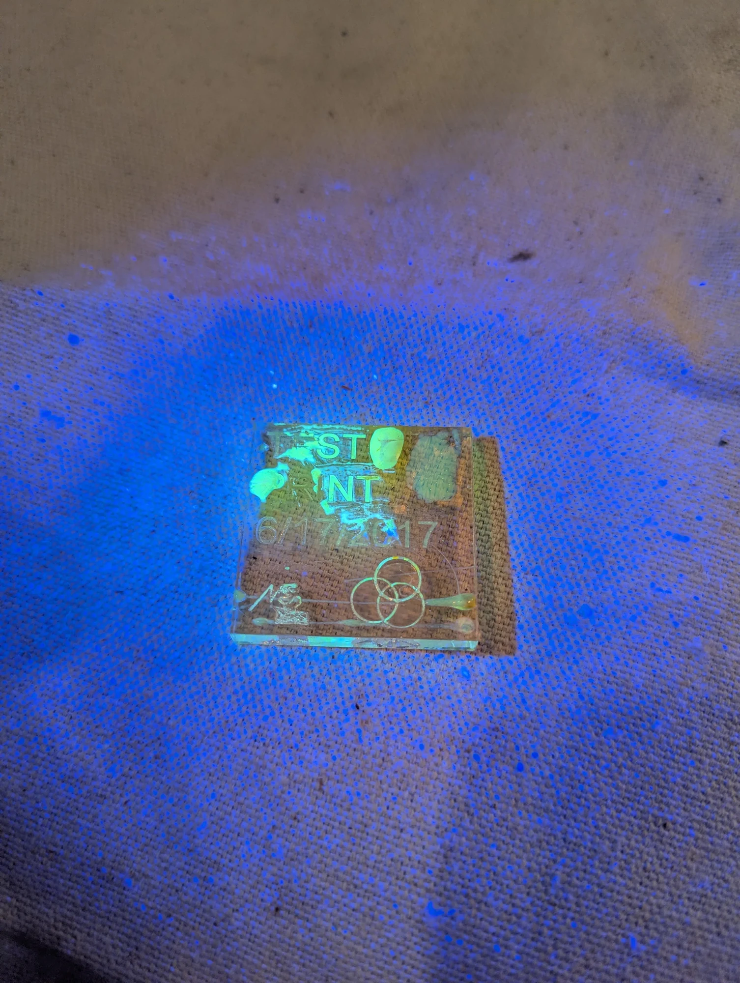
An engraved acrylic piece with fluorescent epoxy pressed into its pattern. Ultraviolet illumination makes the filled areas glow, highlighting the shapes in the surface.
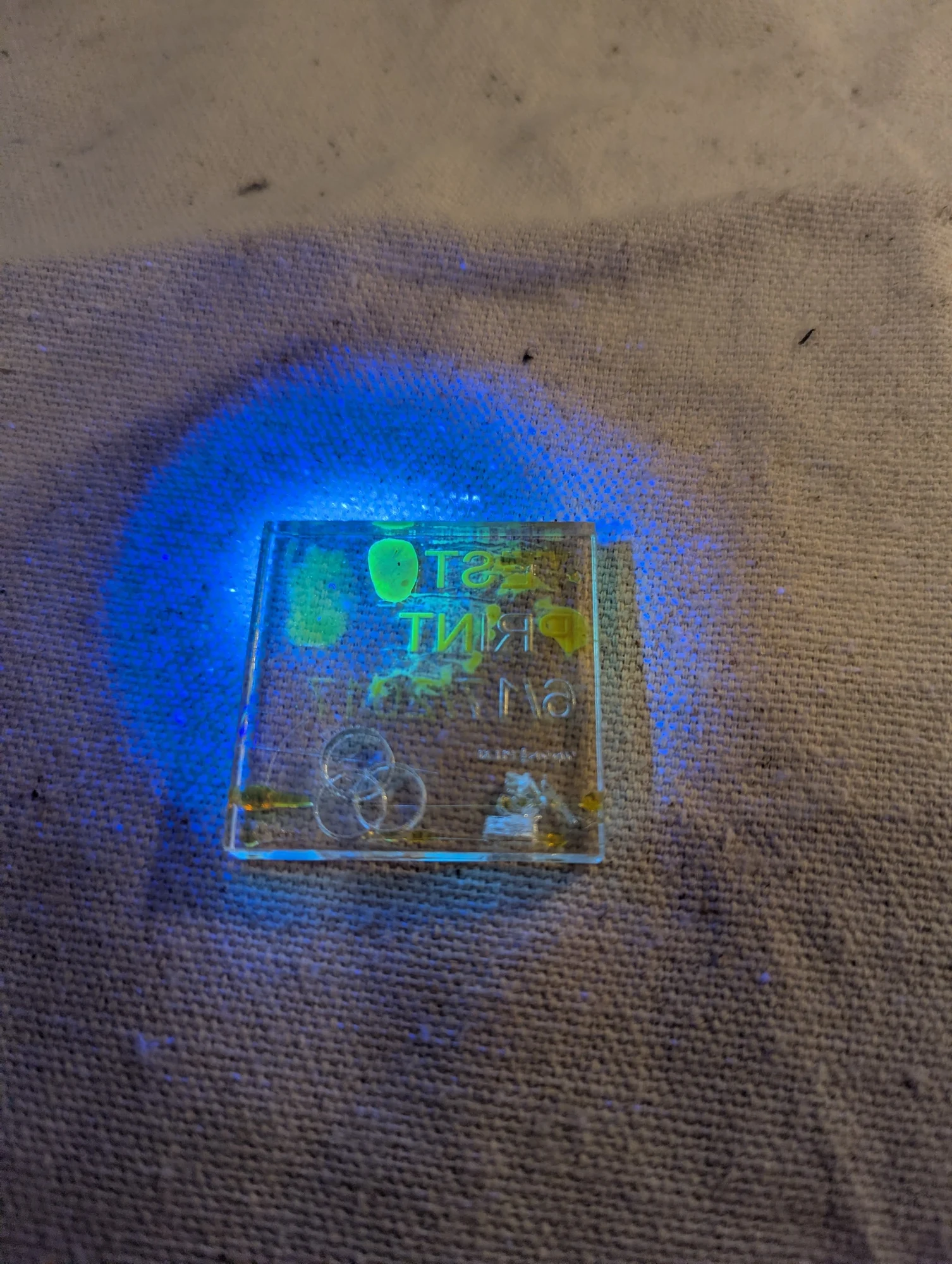
Another view of the engraved acrylic and fluorescent epoxy under ultraviolet light. This was part of the same series of material experiments used to develop the fiber-end fluorescent bead.